Scavenging system for intermittent linear motor

a linear motor and intermittent technology, applied in the direction of mechanical equipment, free piston engines, machines/engines, etc., can solve the problems of unpractical holding a compressed charge for what may be extended periods between cycles, uncompressed combustion chambers and large power output requirements of intermittent linear motors. achieve the effect of simple device, rapid cycle rate, and automatic operation

Inactive Publication Date: 2005-06-09
ADAMS JOSEPH S
View PDF31 Cites 14 Cited by
  • Summary
  • Abstract
  • Description
  • Claims
  • Application Information

AI Technical Summary

Benefits of technology

[0009] In my current invention, a novel approach has been taken to address the problems described above, allowing rapid automatic operation in a simple device. Unlike my U.S. Pat. No. 4,712,379 and U.S. Pat. No. 4,403,722, which rely on a vacuum being set up and manual operations to complete their cycles, exhaust gases can be more completely scavenged within a much shorter time (e.g., 10 milliseconds) in the cycle of my invention. This allows for very rapid cycling rates and minimal heating of the tool. It shares the advantages of my U.S. Pat. Nos. 4,759,318 and 4,665,868 as its cycle can be initiated solely by electric signal without the need for manual pumps or valves, but does not require numerous complicated valves and seals. Thus, it represents a significant advance in efficiency and simplicity of operation over prior art devices.

Problems solved by technology

This is primarily done because holding a compressed charge for what may be extended periods between cycles has not proven practical.
However, as a result of the inherent thermal-to-mechanical output inefficiencies resulting from this lack of compression, the combustion chambers of intermittent linear motors are required to be fairly large for a given power output.
These relatively large uncompressed combustion chambers of intermittent linear motors, as well as being inherently inefficient, are especially sensitive to the presence of residual exhaust gases from previous cycles.
Failure to remove such residual gases will result in a diluted charge and deterioration of burn speed, which is critical when driving a fastener.
Thus, unless such gases can be substantially completely removed and replaced with a clean air / fuel mixture, subsequent cycles will deliver significantly less power.
A critical problem associated with these systems is the speed with which the scavenging operations of this type can be accomplished.
This causes the tool to heat up and lose power as well as severely limiting the operating speed of the tool.

Method used


Image

  • Scavenging system for intermittent linear motor
  • Scavenging system for intermittent linear motor
  • Scavenging system for intermittent linear motor

Examples


Embodiment Construction

[0028] In the drawings, similar features have been given similar reference numerals.

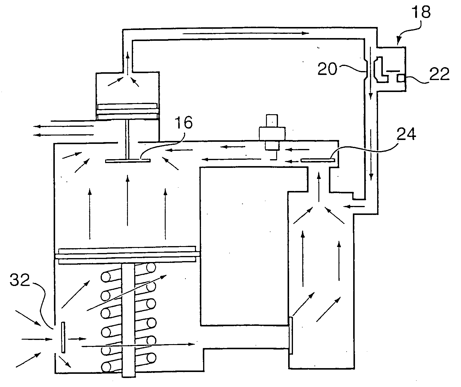
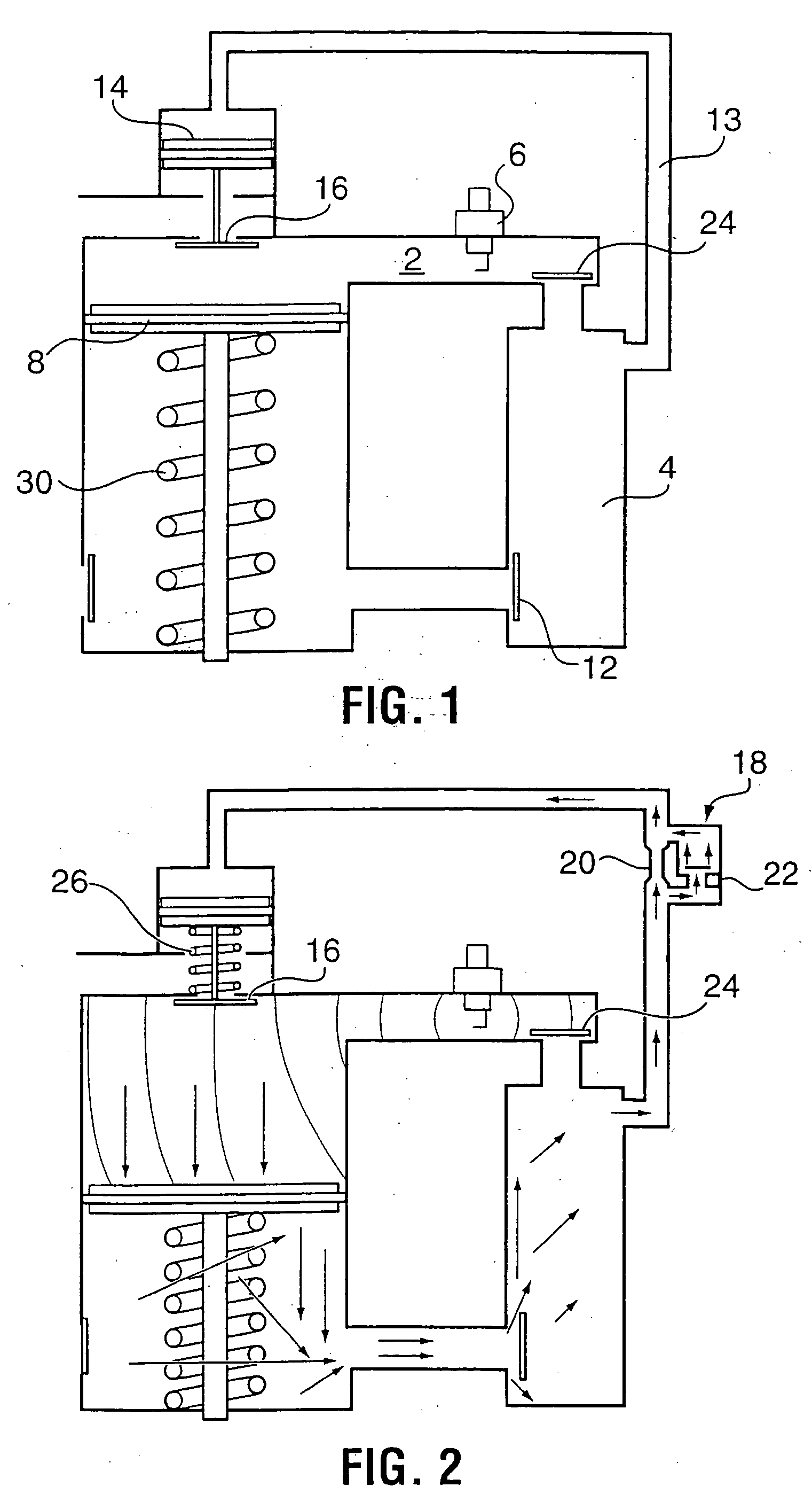
[0029] Turning to FIG. 1, there is shown a schematic view of the intermittent linear motor system for a fastening tool ready for ignition. Fuel injection and starting means are not shown for clarity. At this point, a vapoured fuel such as Mapp gas or propane has been injected into the combustion chamber 2 in the correct proportion to create an explosive fuel / air charge, and the tool is ready to fire as a result of a spark from spark plug 3. Typically, a manual starting pump is connected, preferably to the plenum chamber 4, to provide fresh air to the combustion chamber in the event that unburned gases or inaccurate fueling has left a polluted atmosphere in the combustion chamber as my previous U.S. Pat. Nos. 4,759,318 and 4,665,868 more fully describe.

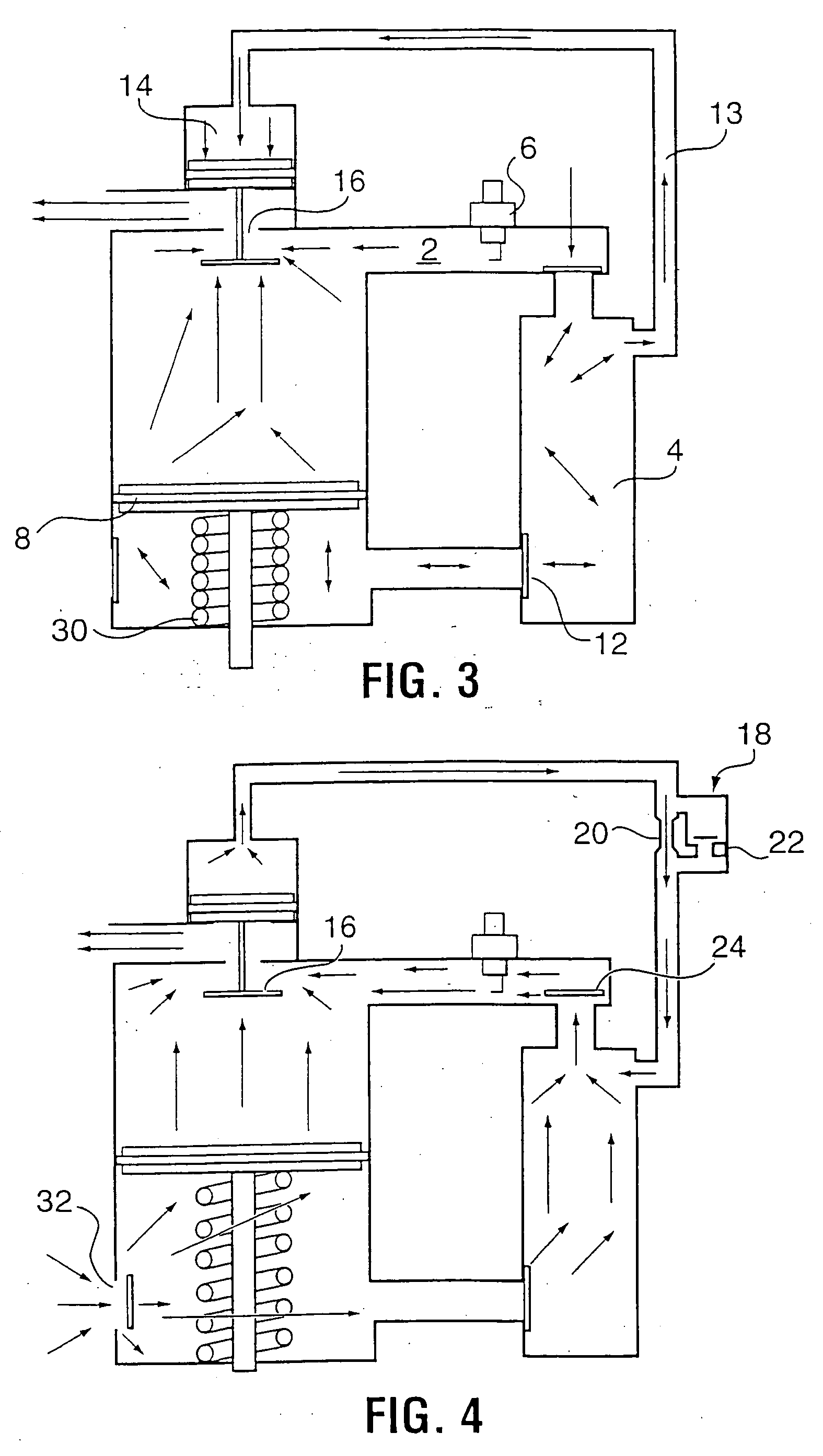
[0030]FIG. 2 shows the combustion mixture being ignited with a spark plug 6 and the power piston 8 being driven down along the piston cylinder throug...


PUM


Abstract

The intermittent linear motor of this invention incorporates features which enhance the exhaust scavenging and cooling processes, as well as simplifying overall construction including a compression plenum below the piston where air displaced during a power stroke by the piston is immediately transferred through the combustion chamber allowing said compressed air to immediately begin scavenging exhaust gases as the piston is returned further displacing spent gases from the motor.

Description

BACKGROUND OF THE INVENTION [0001] 1. Field of the Invention [0002] This invention relates generally to the field of intermittent linear motors for use in combustion gas powered tools such as those used to drive fasteners. [0003] 2. Description of Related Art [0004] The cycle of the intermittent linear motor is different from that of a continuous running engine. It does not continue automatically, as would be the case in a reciprocating internal combustion engine. Instead, the intermittent linear motor's power piston must be returned to, and remain in, a starting or rest position between each power stroke. Typically, a rod fitted to the power piston engages a fastener or other load and mechanical energy is transmitted through the rod to drive a fastener or perform other useful work during the power stroke. [0005] The power piston is returned to its starting or rest position within a piston cylinder during a reciprocation stroke by a resilient member, vacuum draw, or return air press...

Claims


Application Information

Patent Timeline
Patent Type & Authority Applications(United States)
IPC IPC(8): F02B71/00
CPCF02B71/00
Inventor ADAMS, JOSEPH S.
Owner ADAMS JOSEPH S
Why Eureka
Try Eureka