Connecting structure between rotary shaft and metal plate and method of connecting therebetween

a technology of connecting structure and rotary shaft, which is applied in the direction of couplings, manufacturing tools, machines/engines, etc., can solve the problems of increasing cost, inability to obtain satisfactory coaxiality, and restricted inclination of metal plate relative to shaft, so as to reduce manufacturing cost, reduce cost, and precise positioning and holding of metal plate

Active Publication Date: 2005-06-09
HITACHI ASTEMO LTD
View PDF7 Cites 13 Cited by
  • Summary
  • Abstract
  • Description
  • Claims
  • Application Information

AI Technical Summary

Benefits of technology

[0025] Also, even when the gap defined between the small-diameter shaft portion and the mount hole is not so small, the outside diameter of the small-diameter shaft portion and an inside diameter of the mount hole are not precisely adjusted, it is possible to reduce the manufacturing cost.
[0026] Further, in the case of fixedly connecting the metal plate to the rotary shaft at a predetermined angle (posture), it has been conventionally necessary to use a

Problems solved by technology

With the connecting method described in the JP-A-11-192567, however, the metal plate and the shoulder surface on the shaft are joined together by means of laser welding, so that inclination of the metal plate relative to the shaft is restricted.
Also, there is caused a problem that a gap (clearance) is ordinarily defined between the small-diameter shaft portion (projecting shaft portion) and the fitting hole to result in eccentricity of the metal plate (or its fitting hole) relative to the shaft, so that satisfactory coaxiality cannot be obtained.
In this case, it may decrease the gap in order to improve coaxiality, but it is necessary to control an

Method used


Image

  • Connecting structure between rotary shaft and metal plate and method of connecting therebetween
  • Connecting structure between rotary shaft and metal plate and method of connecting therebetween
  • Connecting structure between rotary shaft and metal plate and method of connecting therebetween

Examples


Embodiment Construction

[0040] An embodiment of the invention will be described below with reference to the drawings.

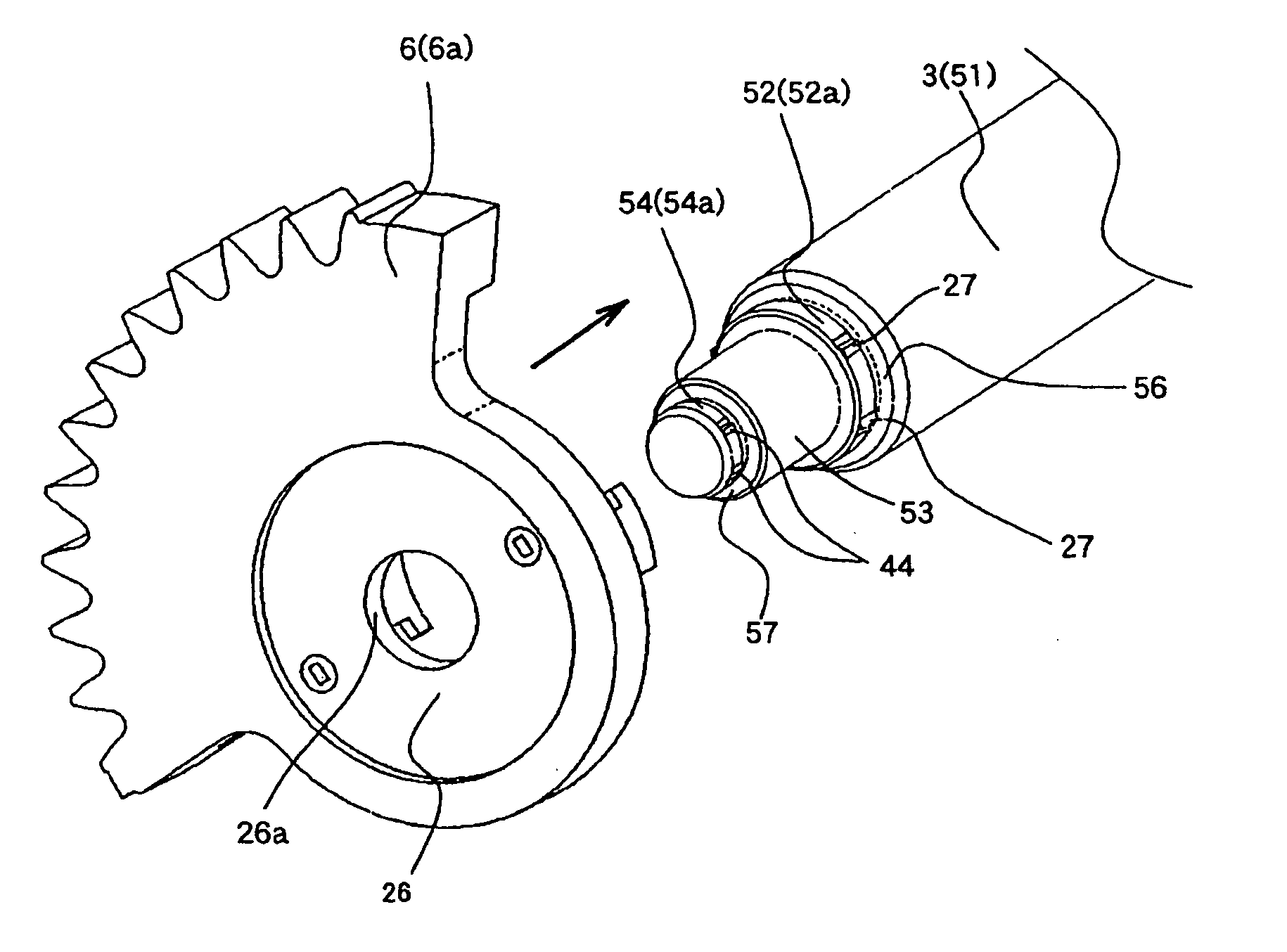
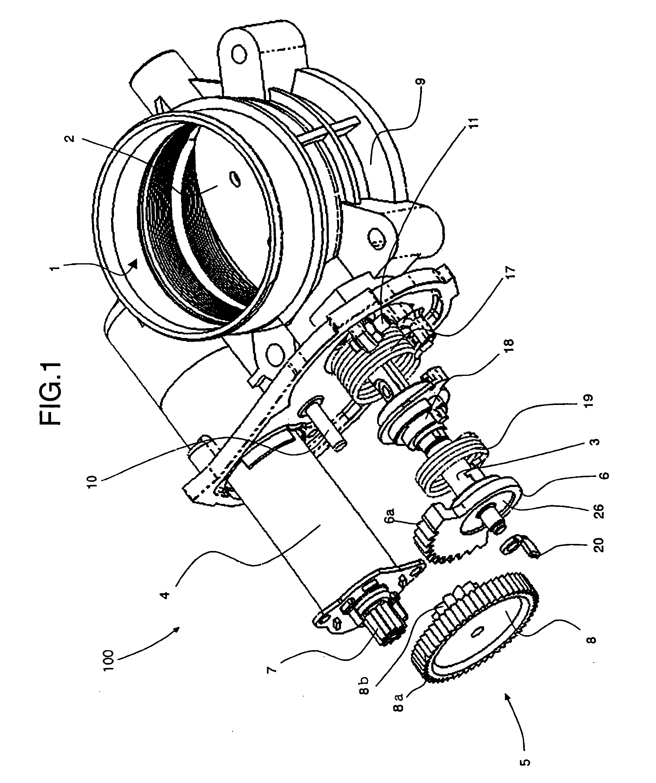
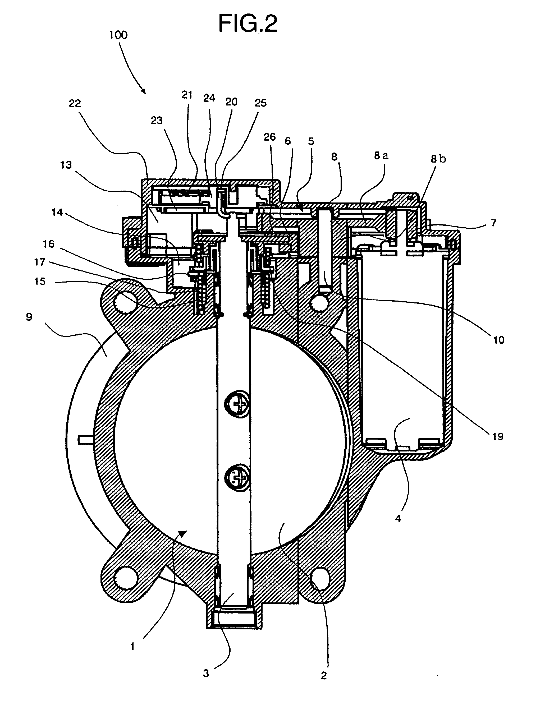
[0041]FIG. 1 is an exploded, perspective view showing an electrically controlled throttle device, to which an embodiment of a connecting structure between a rotary shaft and a metal plate, according to the invention, is applied, with a gear cover being removed, FIG. 2 is a view showing a cross section of the electrically controlled throttle device of FIG. 1 cutting along a plane perpendicular to an intake passage and through an axis of rotation of a valve shaft, and FIG. 3 is a side view showing a gear mounting portion of the electrically controlled throttle device of FIG. 1 with the gear cover being removed.

[0042] A quantity of an air flowing in an intake passage 1 is regulated according to the opening degree of a disk-shaped throttle valve 2 in the electrically controlled throttle device shown in FIGS. 1, 2 and 3. The throttle valve 2 is fixed to a valve shaft 3 as a rotary shaft by scre...


PUM

PropertyMeasurementUnit
Thicknessaaaaaaaaaa
Heightaaaaaaaaaa
Lengthaaaaaaaaaa

Abstract

In a connecting structure between a rotary shaft and a metal plate and a method of connecting them together, in which the metal plate can be joined to the rotary shaft with a high degree of accuracy with high strength at a low manufacturing cost without causing eccentricity, inclination, or the like as far as possible, a large-diameter shaft portion and a small-diameter shaft portion are connected to each other with a predetermined difference in diameter so as to form therebetween a shoulder surface perpendicular to an axis of rotation, plural stripes of coining indents extending in a direction of shaft length are formed on the outer peripheral surface of the small-diameter shaft portion, a circular-shaped mount hole adapted to be fitted onto the small-diameter shaft portion is formed in the metal plate, the mount hole of the metal plate is press-fitted onto the small-diameter shaft portion so as to be subjected to plastic deformation by the coining indents, a portion surrounding the mount hole on one side surface of the metal plate is pushed against the shoulder surface, and the outer peripheral surface of the small-diameter shaft portion and the mount hole of the metal plate are joined together by laser welding or the like.

Description

BACKGROUND OF THE INVENTION [0001] The present invention relates to a connecting structure, in which a rotary shaft, such as a valve shaft or the like, supporting, for example, a throttle valve, and a metal plate constituting a gear or the like are fixedly connected to each other so as to be able to rotate together, and a connecting method therefor. [0002] For example, JP-A-11-192567 (pages 1 to 8, and FIGS. 1 to 11) describes, as a known technique of joining a rotary shaft and a metal plate together, a method, in which a large-diameter shaft portion (central shaft) and a small-diameter shaft portion (projecting shaft portion) are connected to each other with a step therebetween so as to define a shoulder surface orthogonal to a central axis, a circular fitting hole fitted therein the small-diameter shaft portion is formed on the metal plate, the fitting hole of the metal plate is then fitted onto the small-diameter shaft portion, and then the metal plate and the shoulder surface ar...

Claims


Application Information

Patent Timeline
IPC IPC(8): F16B11/00B21K25/00F02D11/10F16D1/072F16D1/08F16D1/09
CPCB21K25/00F02D11/10Y10T29/49945F16D1/0858F16D1/072
Inventor KOBAYASHI, MASAYUKIHARADA, KOJIURAKI, KEIICHIEJIRI, YUKI
Owner HITACHI ASTEMO LTD
Why Eureka
Try Eureka