Method and apparatus for producting negative and positive oxidative reductive potential (orp) water

a technology of oxidative reductive potential and negative and positive ph, which is applied in the direction of water/sewage treatment by electrochemical methods, instruments, disinfection, etc., can solve the problems of significant drop in ph, difficulty in imposing electrical energy or current through, and inability to obtain practical matter, etc., to achieve effective, efficient and economical

Active Publication Date: 2005-06-09
SONOMA PHARMA INC
View PDF99 Cites 101 Cited by
  • Summary
  • Abstract
  • Description
  • Claims
  • Application Information

AI Technical Summary

Benefits of technology

[0024] The method and apparatus for producing ORP water of the present invention provides a more effective, efficient, and economical means for electrolytically producing oxidation reduction potential water from aqueous salt solutions for use in disinfection, sterilization, decontamination, wound cleansing, and the like. It accomplishes this objective by providing an electrolysis unit having a novel three compartment cell comprising a cathode chamber, an anode chamber, and a saline solution chamber interposed therebetween. Two communicating membranes separate the three chambers. The center chamber include a fluid flow inlet and outlet and contains insulative material that ensures direct voltage potential does not travel through the chamber. A supply of water flows through the cathode and anode chambers at the respective sides of the saline chamber. Saline solution flows through the center chamber, either by circulating a pre-prepared aqueous solution containing ionic species, or, alternatively, by circulating pure water or an aqueous solution of, e.g., aqueous hydrogen chloride and ammonium hydroxide, over particulate insulative material coated with a solid electrolyte. Electrical current is provided to the communicating membranes separating the chambers, thus causing an electrolytic reaction that produces both oxidative (positive) and reductive (negative) ORP water having pH levels ranging from approximately 8 to 12. The reductive water is dispensed into a collecting chamber main tank that contains inert atmosphere (preferably nitrogen), an ultrasonic agitation system, and an inductive heater. the oxidative water is drained to a second storage chamber.

Problems solved by technology

It is difficult to force electrical energy, or current, through pure water since it is not a charge carrier and is not ionic in and of itself.
Absolutely pure water, while theoretically simple is, as a practical matter, virtually impossible to obtain.
The resulting hydrochloric acid, HCl, can cause a significant drop in pH.
The production of atomic oxygen is possible; however due to the instability it is not present for long or in high concentration.
However, only recently have developments in the art of electrolysis provided an alternative method of microbial disinfection and sterilization.
Super-oxidized water has a limited shelf life and decreasing activity over time.
While it is well known to utilize an ion selective barrier between the anode and cathode chambers of an electrolysis unit, to date it is not known to provide a supply of flowing ionic solutions in a chamber intermediate the anode and cathode chambers to facilitate the production of oxidative reduction potential (ORP) water.

Method used


Image

  • Method and apparatus for producting negative and positive oxidative reductive potential (orp) water
  • Method and apparatus for producting negative and positive oxidative reductive potential (orp) water
  • Method and apparatus for producting negative and positive oxidative reductive potential (orp) water

Examples


Embodiment Construction

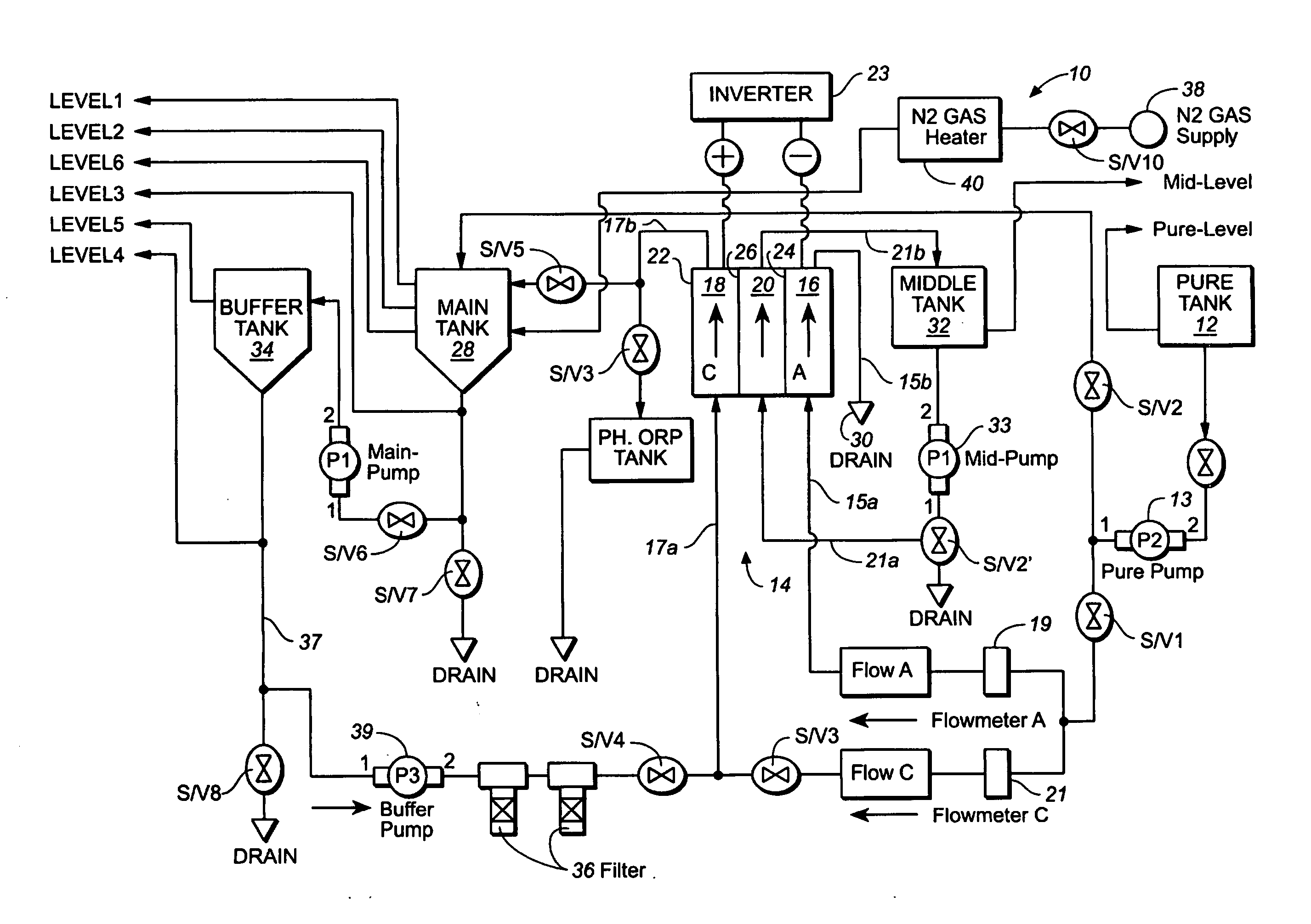
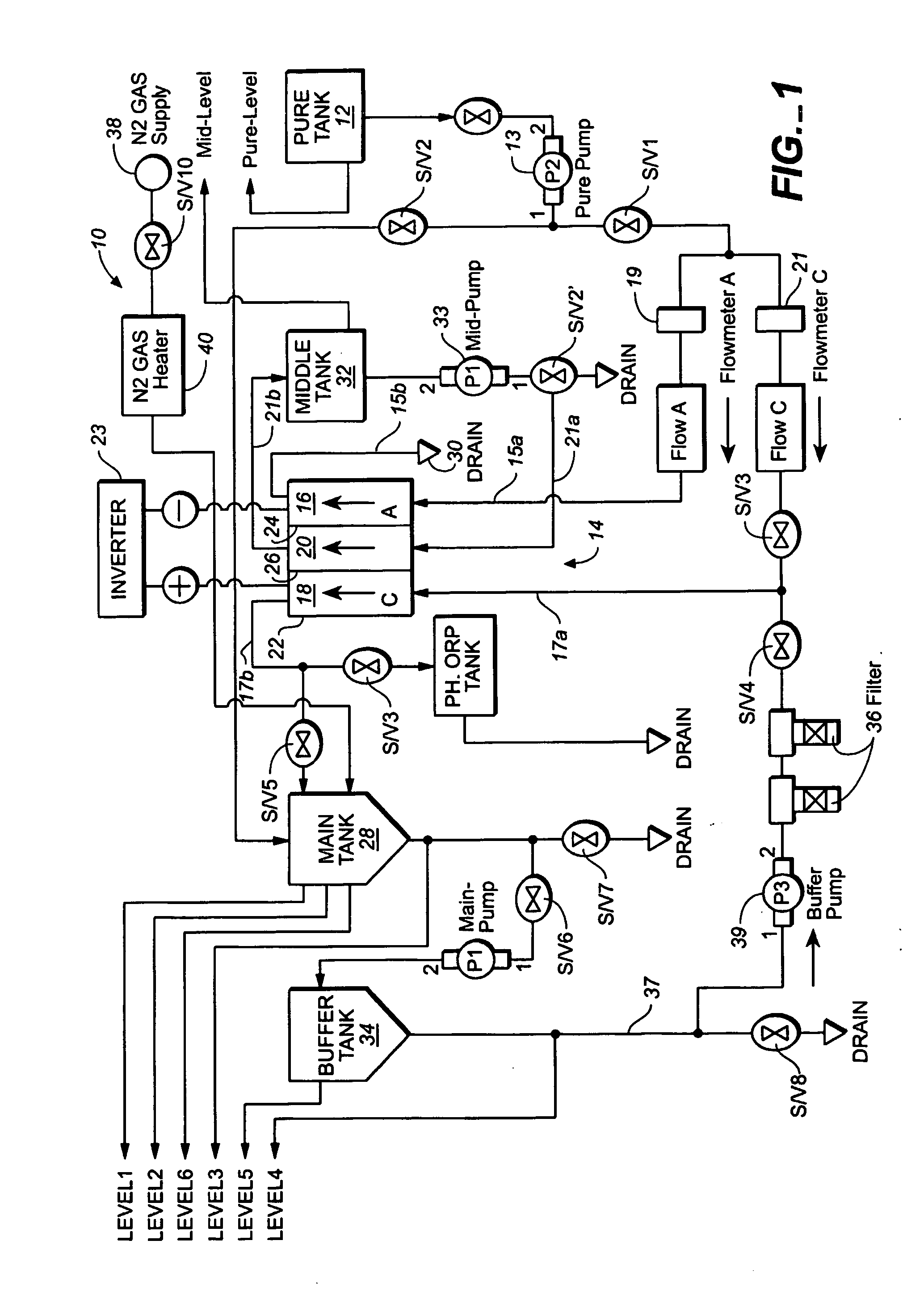
[0033] Referring to FIGS. 1 through 6, wherein like reference numerals refer to like components in the various views, FIG. 1 is a schematic diagram of the inventive apparatus for producing positive and negative ORP water of the present invention. This view shows that the inventive device, generally denominated 10, comprises a unique electrolysis system which utilizes a three-chambered electrolysis unit or cell specifically adapted for producing ORP water. The system includes a water inlet tank 12 in fluid communication with an electrolysis unit 14 having an anode chamber 16, a cathode chamber 18, and a saline solution chamber 20 interposed between the anode and cathode chambers.

[0034] Referring now to FIGS. 1, 3 and 4, the three chambers of the electrolysis unit are enclosed in a housing 22 in which are inserted a metal anode electrode membrane 24 facing the anode chamber, a first ion exchange membrane 25 approximated or mated to the anode electrode and separating the anode chamber...


PUM

PropertyMeasurementUnit
flow rateaaaaaaaaaa
pHaaaaaaaaaa
flow rateaaaaaaaaaa

Abstract

A method and apparatus for electrolytically producing oxidation reduction potential water from aqueous salt solutions for use in disinfection, sterilization, decontamination, wound cleansing. The apparatus includes an electrolysis unit having a three-compartment cell (22) comprising a cathode chamber (18), an anode chamber (16), and a saline solution chamber (20) interposed between the anode and cathod chambers. Two communicating (24, 26) membranes separate the three chambers. The center chamber includes a fluid flow inlet (21a) and outlet (21b) and contains insulative material that ensures direct voltage potential does not travel through the chamber. A supply of water flows through the cathode and anode chambers at the respective sides of the saline chamber. Saline solution flows through the center chamber, either by circulating a pre-prepared aqueous solution containing ionic species, or, alternatively, by circulating pure water or an aqueous solution of, e.g., aqueous hydrogen chloride and ammonium hydroxide, over particulate insulative material coated with a solid electrolyte. Electrical current is provided to the communicating membranes separating the chambers, thus causing an electrolytic reaction that produces both oxidative (positive) and reductive (negative) ORP water.

Description

BACKGROUND OF THE INVENTION [0001] 1. Technical Field [0002] The present invention relates generally to acidic and alkaline / oxidative and reductive potential water (ORP water) and to methods of electrolyzing saline solutions. More particularly, the present invention relates to a method and apparatus for producing negative and positive ORP water, and the water so produced, for use in sterilization, decontamination, disinfection, skin cleansing, and wound healing catalysis. [0003] 2. Background Art [0004] The production of super-oxidized water is an electrochemical, or oxidation-reduction process. This is commonly referred to as an electrolytic or redox reaction in which electrical energy is used to produce chemical change in an aqueous solution. Electrical energy is introduced into and transported through water by the conduction of electrical charge from one point to another in the form of an electrical current. In order for the electrical current arise and subsist there must be char...

Claims


Application Information

Patent Timeline
Patent Type & Authority Applications(United States)
IPC IPC(8): C02F1/46A61L2/03A61L2/18C02F1/461C25B9/00C25C1/02
CPCC02F2001/46195C02F1/4618C02F2201/46115C02F2201/4613C02F2201/46145C02F2201/4618C02F2201/46195C02F2209/04C02F2209/06C02F2303/04Y02E60/366A61L2/035A61L2/183A61L2/186A61L2202/11C02F1/46104C02F1/46114C02F2201/4611Y02E60/36
Inventor SUMITA, OSAO
Owner SONOMA PHARMA INC
Why Eureka
Try Eureka