EER modulator with power amplifier having feedback loop providing soft output impedance

a technology of power amplifier and feedback loop, which is applied in the field of wideband power amplifier improvement, can solve the problems of insufficient technique for combining the outputs of two different amplifiers, difficulty in comparing the output impedances of high frequency and power amplifiers, and achieve high efficiency power

Active Publication Date: 2005-06-09
NORTHROP GRUMMAN SYST CORP
View PDF8 Cites 90 Cited by
  • Summary
  • Abstract
  • Description
  • Claims
  • Application Information

AI Technical Summary

Benefits of technology

[0023] (b) an output coupled to the current control input of the high efficiency power amplifier.
[0024] The high efficiency power amplifier has a first gain and the feedback control loop has a second gain, and the product of the first and second gains provides an active resi

Problems solved by technology

The difficulty arises in combining the outputs of the two amplifiers so as to obtain a faithful amplified reproduction of the envelope signal A(t).
The technique for combining the outputs of the two different amplifiers disclosed in the above-referenced patent to Mathe et al. has been found to be inadequate.
In consideri

Method used


Image

  • EER modulator with power amplifier having feedback loop providing soft output impedance
  • EER modulator with power amplifier having feedback loop providing soft output impedance
  • EER modulator with power amplifier having feedback loop providing soft output impedance

Examples


Embodiment Construction

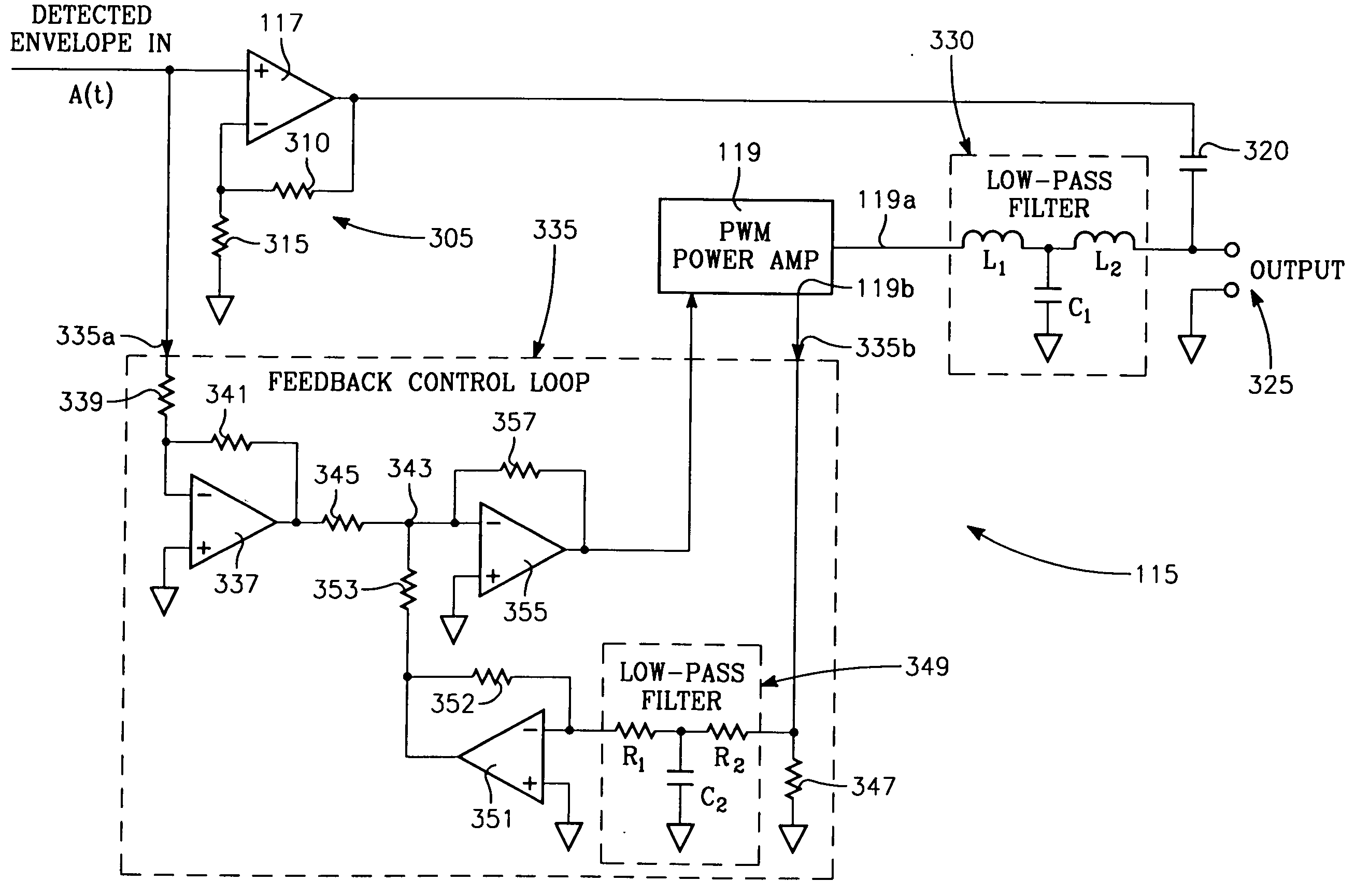
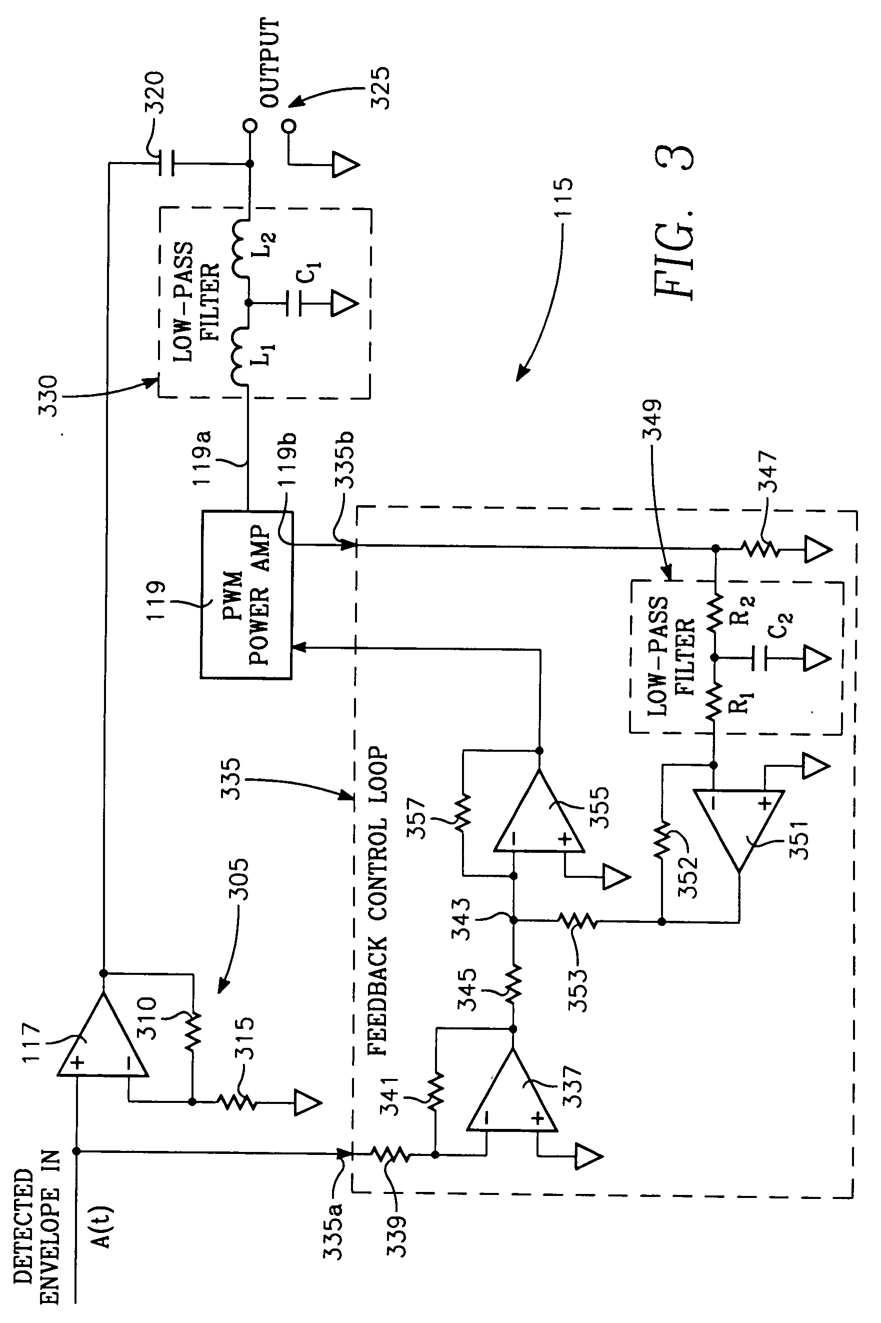
[0030] The problems referred to above in the background discussion are solved in the present invention by a novel feedback loop in the EER modulator that minimizes differences between the output impedances of the high efficiency power amplifier and high frequency voltage operational amplifier. In this feedback loop, the power amplifier is servoed so as to minimize differences between its output current and the actual envelope signal. Furthermore, the gain of the feedback loop and the gain of the power amplifier are selected to fix the active output resistance of the power amplifier at a level that is compatible with the output resistance of the high frequency operational amplifier. Preferably, this level corresponds to a “soft” output impedance on the order of about 5-10 Ohms and more preferably about 6 Ohms, depending upon the output impedance of the high frequency amplifier. In this way the power amplifier combines the advantages of both a low impedance voltage source and a high p...


PUM


Abstract

An EER amplifier for amplifying an RF signal includes: (II) a first RF amplifier for amplifying the phase portion of the signal; (III) an EER modulator for amplifying the envelope or baseband portion of the signal, including: A) a high frequency operational amplifier; B) a power amplifier; C) a feedback control loop including:
        • (1) a current-to-voltage conversion amplifier having an input coupled to a current monitoring output of the power amplifier and an output,
        • (2) an input buffer amplifier having an input coupled to receive the envelope signal and an output;
        • (3) a summing amplifier having: (a) an input coupled to the outputs of: (a) the current-to-voltage conversion amplifier and (b) the input buffer amplifier, and (b) an output coupled to the current control input of the power amplifier.

Description

BACKGROUND OF THE INVENTION [0004] The invention concerns improvements in wideband power amplifiers for communication or RF signals and in particular to power amplifiers employing envelope elimination and restoration (EER) of the type disclosed in U.S. Pat. No. 6,300,826 to Mathe et al. [0005] An EER amplifier separates an incoming complex signal, A(t)ej(ωt+φ(t)), into two channels, the amplitude channel carrying A(t) and phase channel carrying ej(ωt+φ(t)); where φ(t) is the time-dependent phase of the incoming signal, ω is the carrier frequency and A(t) is the amplitude or envelope. The envelope A(t) has frequency bandwidth from DC to the maximum base band frequency, while the phase channel retains the original carrier frequency and contains only the phase information after the amplitude or envelope A(t) is eliminated. A highly linear power amplifier, such as a class AB amplifier, amplifies the signal in the phase channel. The envelope is restored in the amplified signal by an EER ...

Claims


Application Information

Patent Timeline
IPC IPC(8): H03F1/02H03F3/217H03F3/68
CPCH03F1/0227H03F3/68H03F3/217
Inventor CHU, PETER F.
Owner NORTHROP GRUMMAN SYST CORP
Why Eureka
Try Eureka