
Method and apparatus for video and image deinterlacing and format conversion

Active Publication Date: 2005-06-09
AVAGO TECH INT SALES PTE LTD
View PDF3 Cites 47 Cited by
  • Summary
  • Abstract
  • Description
  • Claims
  • Application Information

AI Technical Summary

Benefits of technology

[0011] The objects, features and advantages of the present invention include providing a method and apparatus for video and image deinterlacing and format conversion that may (i) utilize only a modest amount of silicon, (ii) uses minimal memory bandwidth to operate, (iii) operate on a small integer number of line buffers from each field, (iv) perform minimal arithmetic operations, (v) produce improved quality compared with conventional approaches, (vi) achieve a good trade-off between reducing flicker, reducing interlace artifacts, retaining high vertical frequencies and rendering edges smoothly, (vi) generate better looking edges than with plain motion adaptive or motion compensated deinterlacing, (vii) generate better looking non-edge regions than with purely edge-based interpolation or other purely spatial-based interpolation techniques and / or (viii) effectively reduce blocking artifacts while permitting individual filtering methods to contribute best performances to improving quality in local regions thru a combination of picture and pixel-level adaptive and / or non-adaptive switching and / or blending between the alternative methods.

Problems solved by technology

Vertical filtering is known to produce temporal flickering artifacts in video and significantly reduced vertical detail in both images and video.
The lack of vertical detail is particularly noticeable for sharp edges.
Temporal filtering is known to produce “jaggies”.
Jaggies a re interlace artifacts that are extremely objectionable for moving objects.
The VT-filtering is a low-cost line-based process that is cost effective to implement in silicon, but is known to produce temporal artifacts.
Weave is the best option for still portions of video, while a poor choice for moving areas.
Hard block-level decisions can lead to objectionable blocking artifacts.
However, more advanced motion adaptive deinterlacing techniques that combine weave and bob suffer mainly from relatively poor performance for moving video, for which all of the drawbacks of bob are encountered.
A disadvantage of motion compensated technique is that motion estimation is typically far more expensive than any of the previously mentioned techniques.
Furthermore, if motion estimation fails on the video sequence (i.e., highly irregular motion, non-smooth motion fields or various lighting effects may cause motion estimation to fail), then motion compensated techniques can be no better than less complex methods.
In practice, however, motion compensated deinterlacing greatly increases vertical detail, while greatly reducing flickering artifacts on a broad range of video, such that the main drawback is complexity.
To a lesser extent than vertical filtering, edge-based spatial filtering also suffers from lack of vertical detail.
In particular, high frequency textures that lack edges will not be improved over simple vertical filtering.

Method used


Image

  • Method and apparatus for video and image deinterlacing and format conversion
  • Method and apparatus for video and image deinterlacing and format conversion
  • Method and apparatus for video and image deinterlacing and format conversion

Examples


Embodiment Construction

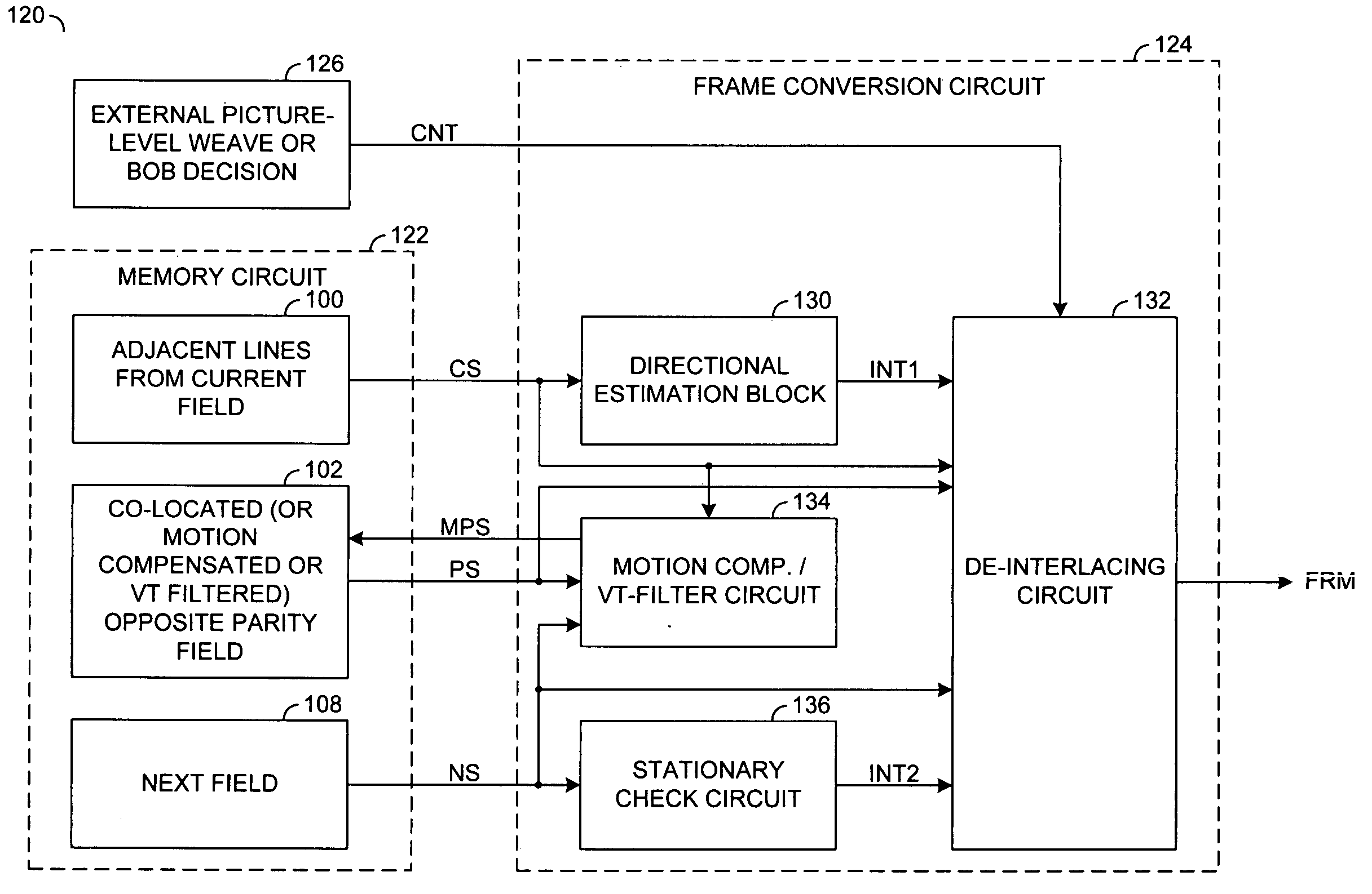
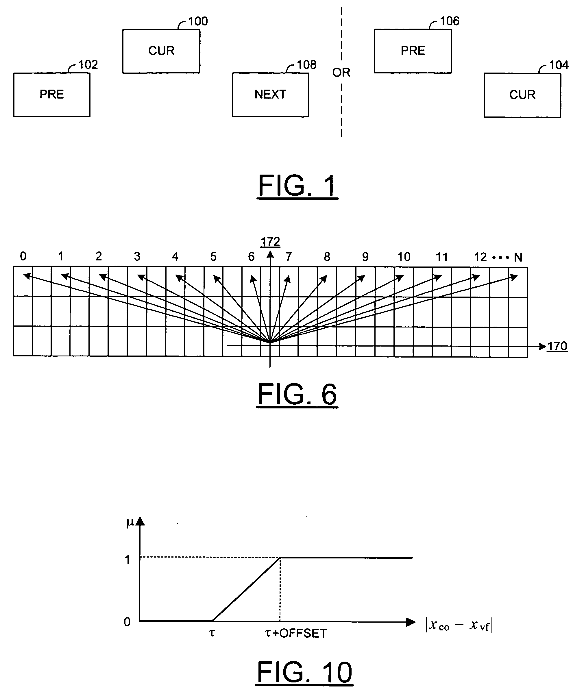
[0023] The present invention is best realized as a very low-cost, but high quality deinterlacing process, method, apparatus and / or architecture. The invention may be referred to as a reduced enhanced motion adaptive deinterlacing (REMADI) architecture. High quality may be realized through the several attributes of the method. The REMADI approach may adaptively select and blend picture-level and pixel-level switching and blending mechanism estimates for pixels or luminance samples located between the horizontal field lines of a current field. The estimates may be based upon (i) previous field pixels (e.g., weave), (ii) a vertical filtered interpolation from the current field (e.g., bob) and / or (iii) a directionally interpolated estimate from the current field. The directional interpolated estimate generally provides an efficient approach that may minimize silicon cost by reducing a bit-depth of a detector and using regular structures such that arithmetic operations may be reduced.

[0...


PUM


Abstract

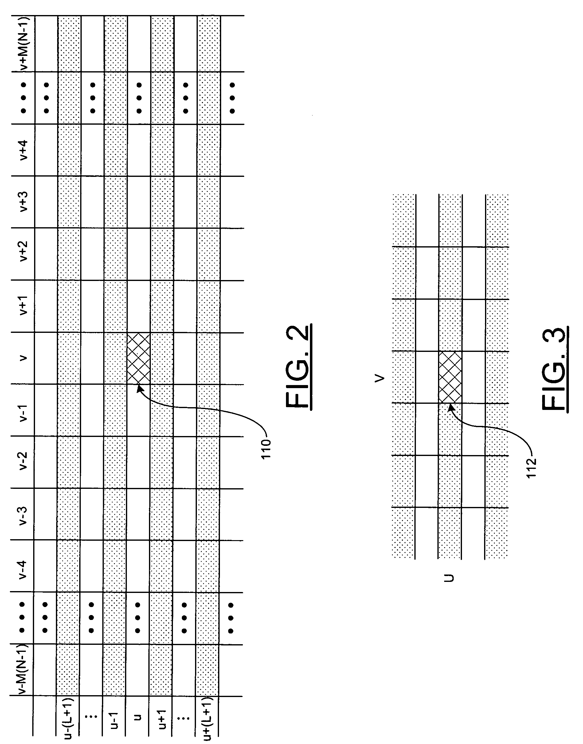
A method and apparatus for deinterlacing a picture is disclosed. The method generally includes the steps of (A) calculating a plurality of differences among a plurality of current samples from a current field of the picture, the differences being calculated along a plurality of line segments at a plurality of angles proximate a particular position between two field lines from the current filed, (B) generating a first sample at the particular position by vertical filtering the current field in response to the differences indicating that the particular position is a non-edge position in the picture and (C) generating a second sample at the particular position by directional filtering the current field in response to the differences indicating that the particular position is an edge position in the picture.

Description

FIELD OF THE INVENTION [0001] The present invention relates to a digital video generally and, more particularly, to a method and apparatus for video and image deinterlacing and format conversion. BACKGROUND OF THE INVENTION [0002] Images and video come in a large variety of formats. For many applications, a conversion between formats is performed. A high-quality, low-cost method for converting the video signals is very useful for such applications as (i) converting interlaced NTSC video at 30 fields / second to progressive video with a similar or larger horizontal and vertical resolution at 60 frames / second for display on progressive televisions, (ii) performing a high-quality “zoom” function on either interlaced or progressive video and (iii) increasing the horizontal and / or vertical resolution of progressive or interlaced video and images. [0003] Existing solutions for video deinterlacing include (i) bob (i.e., vertical spatial filter), (ii) weave (i.e., temporal filter), (iii) VT-f...

Claims


Application Information

Patent Timeline
IPC IPC(8): H04N5/14H04N5/44H04N11/20
CPCH04N7/012H04N5/142
Inventor WINGER, LOWELL L.JIA, YUNWEI
Owner AVAGO TECH INT SALES PTE LTD
Learn More