Illumination compensator for curved surface lithography

a curved surface, lithography technology, applied in the direction of microlithography exposure apparatus, printers, instruments, etc., can solve the problems of incoherent illumination, lens cannot transmit higher-order frequencies, and the image quality of aerial images begins to suffer, so as to achieve effective coupling

Inactive Publication Date: 2005-06-09
ANVIK CORP
View PDF6 Cites 7 Cited by
  • Summary
  • Abstract
  • Description
  • Claims
  • Application Information

AI Technical Summary

Benefits of technology

[0010] This invention provides to a large-area lithography system the capability of patterning onto a curved substrate, using a curved mask in order to achieve a fixed track length for conjugate object and image points, by linearly moving a 1:1 projection lens for compensation on a small-field s...

Problems solved by technology

Aerial image quality begins to suffer when the projection lens can no longer transmit the higher-order frequencies.
Though incoherent illumination provides twice the resolution as that of coherent illumination, higher spatial frequencies suffer from lower contrast in the projected image under incoherent illumination.
On the other hand, a curved mask surface can significantly distort the transmitting illuminating beam, depending on the structure of the mask device, causing sever imag...

Method used


Image

  • Illumination compensator for curved surface lithography
  • Illumination compensator for curved surface lithography
  • Illumination compensator for curved surface lithography

Examples


Embodiment Construction

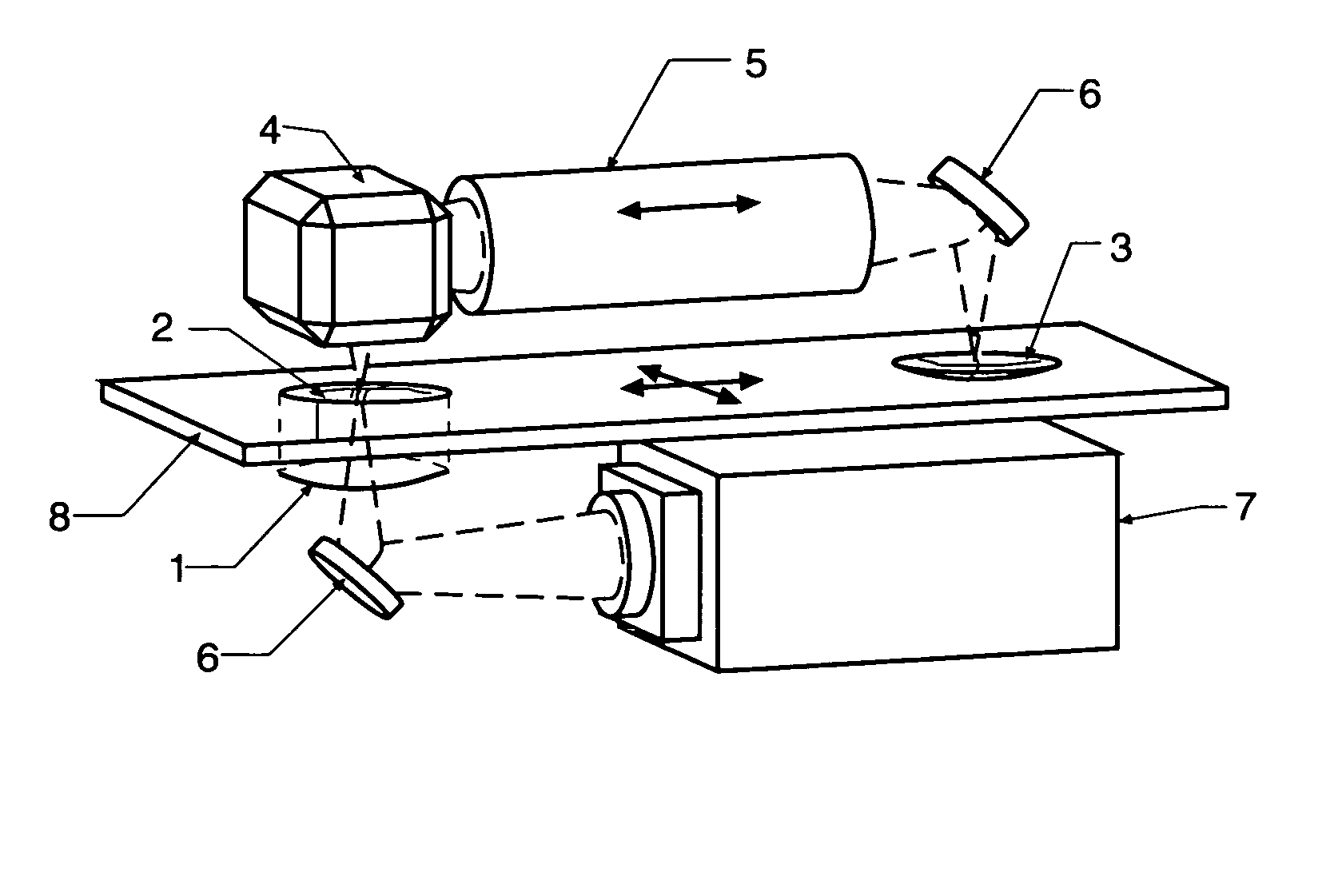
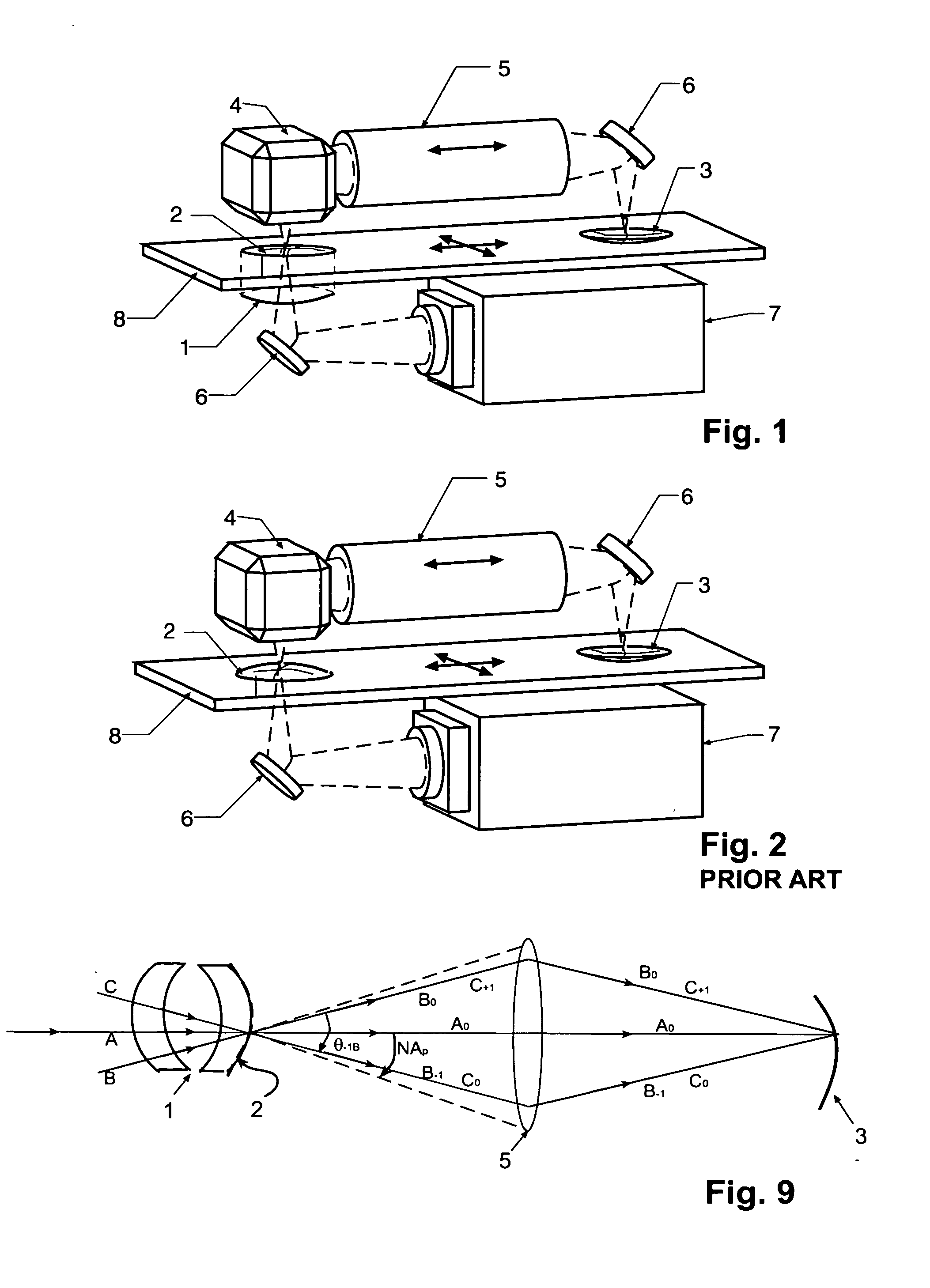
[0026]FIG. 1 and FIG. 2 show the preferred embodiment for patterning onto curved substrates by using a Zerogon lens pair 1, mask 2 having a curvature that is identical to that of the substrate 3 (i.e., the size and shape of the mask 2 and substrate 3 are the same) by additionally performing the imaging using a 1:1 projection imaging system featuring reverser 4, projection lens 5, and fold mirrors 6 as required in directing the patterning beam from illumination source 7 to substrate 3. Stage 8 provides scanning motion. All elements of FIG. 2 (PRIOR ART) are also present in FIG. 1. The difference between the system of FIG. 1 and the PRIOR ART system of FIG. 2 is the presence of the Zerogon in FIG. 1 and the absence of the Zerogon in FIG. 2. The Zerogon in FIG. 1 provides an effective beam coupling between the curved mask and the projection lens.

[0027] We hereby discuss the basis of our invention, initially dealing with planar masks and then with the problems associated with thick cur...


PUM


Abstract

A Zerogon, a zero power identical pair of oppositely-oriented meniscus lens elements mounted in the illumination light path, serves as curved mask support while compensating for optical anomalies such as beam shift and beam deviations produced by other transparent supports for the curved mask. The Zerogon, without affecting the transmission beam characteristics, lets the beam diffract as efficiently as does a regular planar mask, thus preserving the partial coherence parameters and resolution capabilities of projection lithography. This novel optical device is not only expected to clear several barriers for curved mask projection lithography but also find place in other applications where collimated or converging light beams have to travel extra paths without significant aberration in any generic optical system.

Description

(B) CROSS-REFERENCE TO RELATED APPLICATIONS [0001] (Not Applicable) (C) STATEMENT REGARDING FEDERALLY SPONSORED RESEARCH OR DEVELOPMENT [0002] (Not Applicable) (D) REFERENCE TO A MICROFICHE APPENDIX [0003] (Not Applicable) (E) BACKGROUND OF THE INVENTION [0004] (1) Field of the Invention [0005] This invention relates to projection lithography systems for imaging onto 20 curved substrates, and more particularly relates to a large-area lithography system featuring a curved mask that is identical in size and shape to the curved substrate. An axially moving 1:1 projection lens achieves a constant optical path length for conjugate image points in order to maintain the substrate surface within the depth-of-focus, thereby providing an effective depth-of-focus much larger than the depth-of-focus of the projection optics itself. This invention is centered around a novel illumination compensator which we call ‘Zerogon’, that is part of an illumination system and protects the converging illumi...

Claims


Application Information

Patent Timeline
IPC IPC(8): G03B27/58G03F7/20
CPCG03F7/703G03B27/58
Inventor KUCHIBHOTLA, SIVARAMA K.JAIN, KANTIKLOSNER, MARC A.
Owner ANVIK CORP
Why Eureka
Try Eureka