Inflatable cushioning device with manifold system

a cushioning device and manifold technology, applied in the field of fluid cells, can solve the problems of soft tissue damage, soft tissue degeneration, and patients often suffering from the effects of excess pressure transmitted to their bodies, and achieve the effects of minimal maintenance, user controllable, and few moving parts

Inactive Publication Date: 2005-06-16
WCW INC
View PDF99 Cites 70 Cited by
  • Summary
  • Abstract
  • Description
  • Claims
  • Application Information

AI Technical Summary

Benefits of technology

[0008] The present invention provides a cushioning device for a mattress, seat, sofa, or the like where support is obtained from a fluid such as atmospheric air. The cushioning device has few moving parts, is user controllable, requires minimal maintenance, and is easily repairable. The cushioning device of the present invention includes a support system apparatus, a sleeve apparatus, a jacket, a topper cushion, and an outer cover.

Problems solved by technology

In hospitals which provide care to patients confined to a bed for extended periods of time, the patients often suffer from the effects of excess pressure transmitted to their bodies.
As known in the medical field, continuous pressure applied to a patient's body can cause soft tissue damage.
When the external pressure exerted on the patient's skin causes blood carrying capillaries to close, soft tissue degeneration may occur.
This soft tissue damage may lead to the formation of pressure sores.
For example, continuous pressure applied to a patient's heel can cause a pressure sore to develop on the heel.
A problem may develop when the atmospheric pressure at the inflation location is different from the atmospheric pressure at the field location where the device is used.
Such beds are very expensive and require the operator to undergo extensive training to learn how to use and operate the system.
Furthermore, the “treatment products” often require extensive maintenance due to the failure of the numerous moving mechanical parts.
Also, these complicated pressure relief support systems cannot be used on typical box spring mattress supports, and require specialized bed frames.
The complicated design of these beds makes their repair very difficult, and often requires the complete replacement of the entire system for proper servicing.
A further difficulty is that during power outages, these mattresses lose pressure leaving a patient on a hard surface to develop pressure sores if action is not taken.

Method used


Image

  • Inflatable cushioning device with manifold system
  • Inflatable cushioning device with manifold system
  • Inflatable cushioning device with manifold system

Examples


Embodiment Construction

[0057] Although certain preferred embodiments of the present invention will be shown and described in detail, it should be understood that various changes and modifications may be made without departing from the scope of the appended claims. The scope of the present invention will in no way be limited to the number of constituting components, the materials thereof, the shapes thereof, the relative arrangement thereof, etc., and are disclosed simply as an example of the preferred embodiment. The features and advantages of the present invention are illustrated in detail in the accompanying drawings, wherein like reference numerals refer to like elements throughout the drawings. Although the drawings are intended to illustrate the present invention, the drawings are not necessarily drawn to scale.

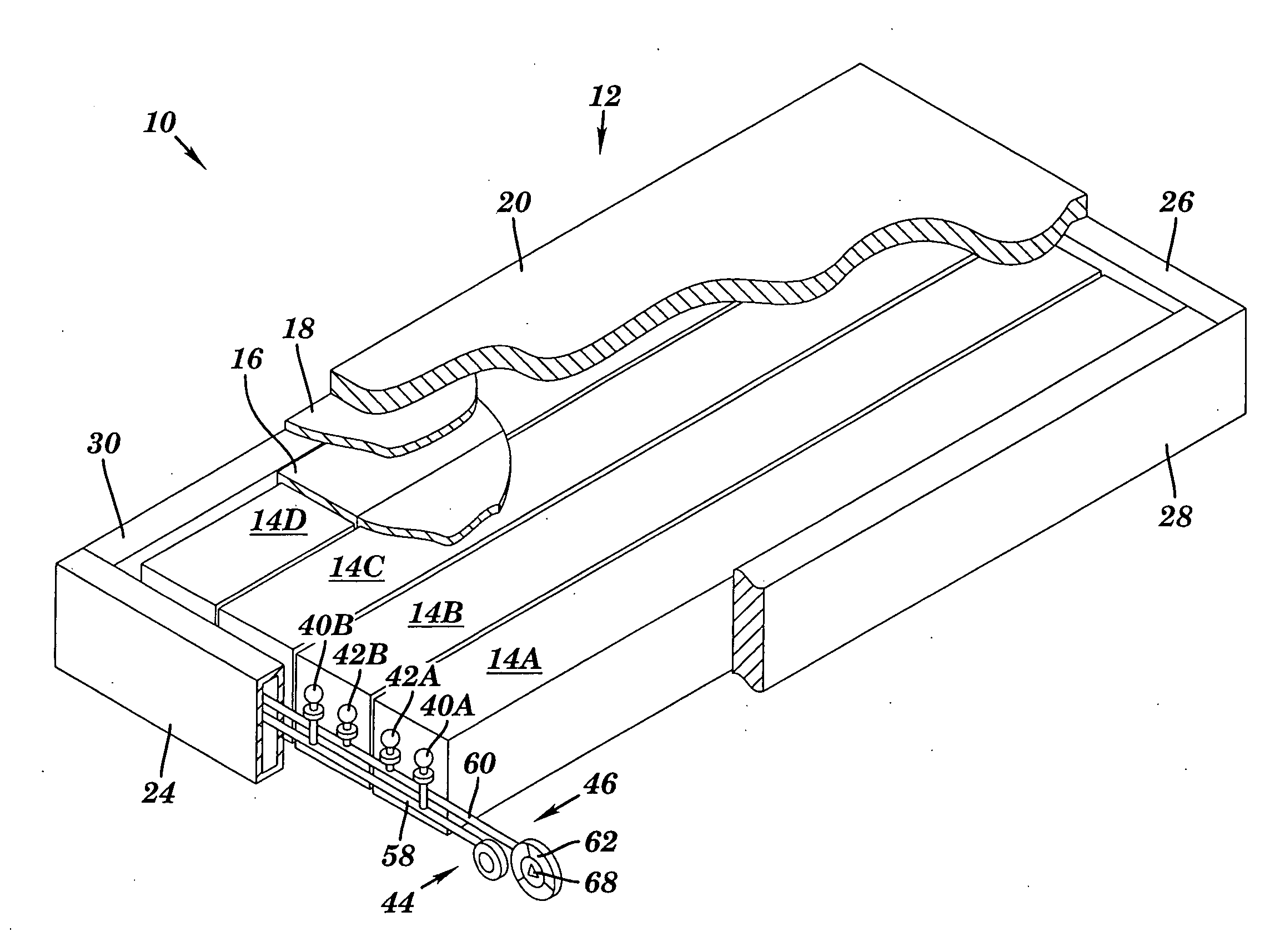
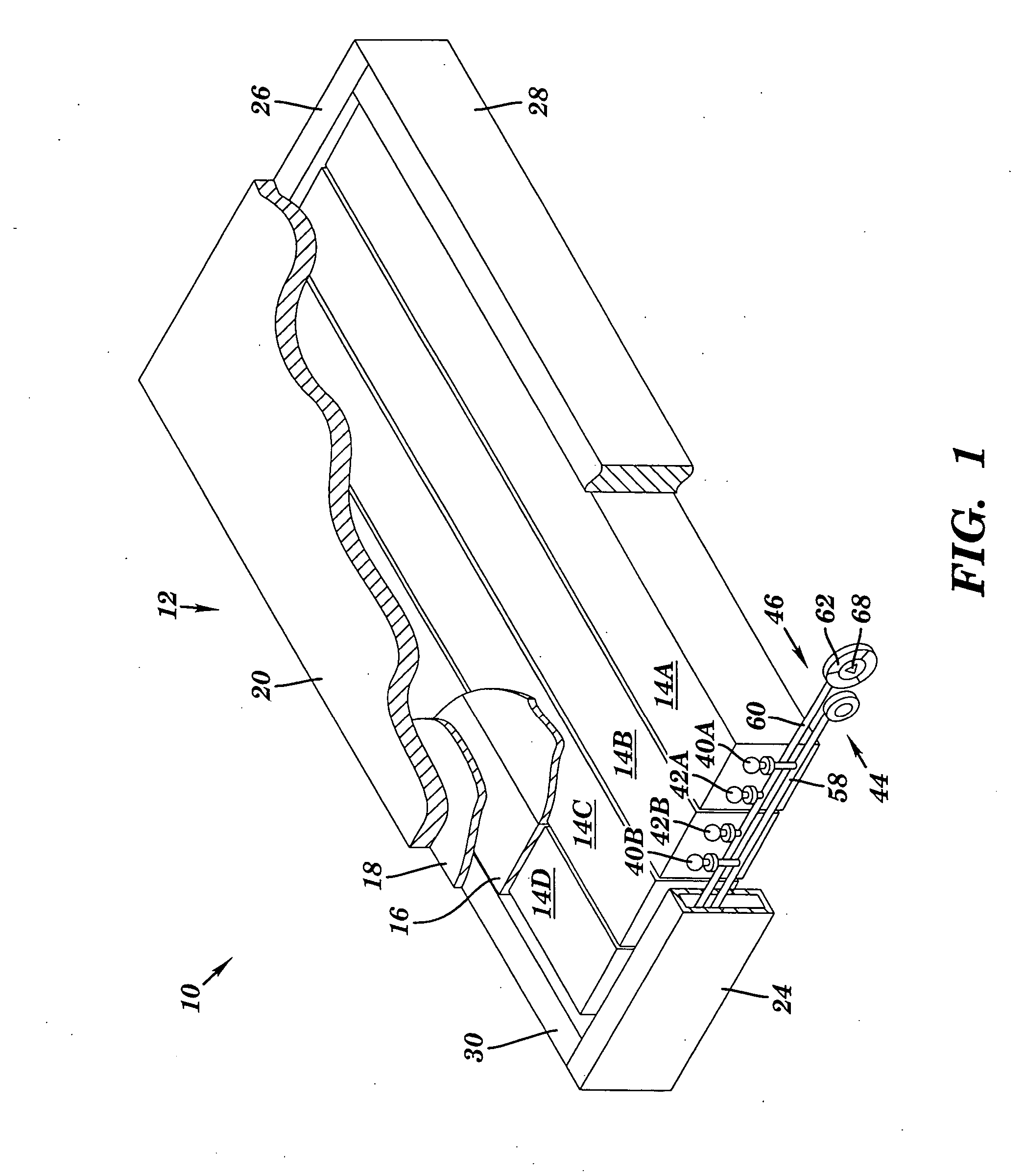
[0058] Referring to FIG. 1, there is illustrated a perspective view of a cushioning device 10 in accordance with a preferred embodiment of the present invention. The cushioning device 10 can ...


PUM


Abstract

A cushioning device for a body support such as a mattress, seat, sofa, or the like where support is obtained from a fluid in fluid cells having a spring bias. The cushioning device is self-inflating, self-adjusting, and provides a low interface pressure under the entire contact surface of a patient. Shear force scraping damage is prevented by a sleeve apparatus. A support system apparatus provides separately adjustable pressure support zones. For physical therapy, an alternating pressure system provides alternating lifting and lowering pressure zones under a patient.

Description

CROSS REFERENCE TO RELATED APPLICATIONS [0001] The present patent application is a continuation-in-part of a copending non-provisional U.S. patent application Ser. No. 10 / 404,962, filed Mar. 31, 2003 by the present inventor and entitled “Inflatable Cushioning Device With Manifold System,” which is a continuation application of U.S. patent application Ser. No. 09 / 867,308, filed Mat 29, 2001 by the present inventor which is a divisional of U.S. patent application Ser. No. 09 / 295,139, filed on Apr. 20, 1999 by the present inventor. In addition, the present application claims the benefit of Provisional Patent Application Ser. No. 60 / 544,366, filed Feb. 13, 2004 by the present inventor.FIELD OF THE INVENTION [0002] The present invention relates generally to a fluid cell for use in a mattress or support surface which allows for discrete support of a body and a support surface which allows for discrete support of a body. The present invention includes reforming elements that are resilient ...

Claims


Application Information

Patent Timeline
Patent Type & Authority Applications(United States)
IPC IPC(8): A47C27/10A61G7/057
CPCA47C27/082A47C27/083A47C27/084A61G7/05776A47C27/10A47C27/18A61G7/05769A47C27/088
Inventor WILKINSON, JOHN
Owner WCW INC
Why Eureka
Try Eureka