Diagnostic system and method for a valve

a valve and diagnostic system technology, applied in the direction of service pipe systems, instruments, transportation and packaging, etc., can solve the problems of structure-borne noise, no diagnostic statement regarding leakage detection is currently possible, etc., and achieve the effect of improving the reliability of the diagnostic resul

Inactive Publication Date: 2005-06-16
SIEMENS AG
View PDF10 Cites 43 Cited by
  • Summary
  • Abstract
  • Description
  • Claims
  • Application Information

AI Technical Summary

Benefits of technology

[0006] An object of the invention is to provide a diagnostic system and a diagnostic method, which have an improved reliability of the diagnostic result.

Problems solved by technology

The causes for the basic noise are essentially the operating noise of the valve drive and the structure-borne noise of neighboring pumps in the process plant, which is transmitted over the pipes.
In this case, the diagnostic result that could at most be indicated, however, is that no diagnostic statement regarding leakage detection is currently possible on the basis of the structure-borne noise.

Method used


Image

  • Diagnostic system and method for a valve
  • Diagnostic system and method for a valve
  • Diagnostic system and method for a valve

Examples


Embodiment Construction

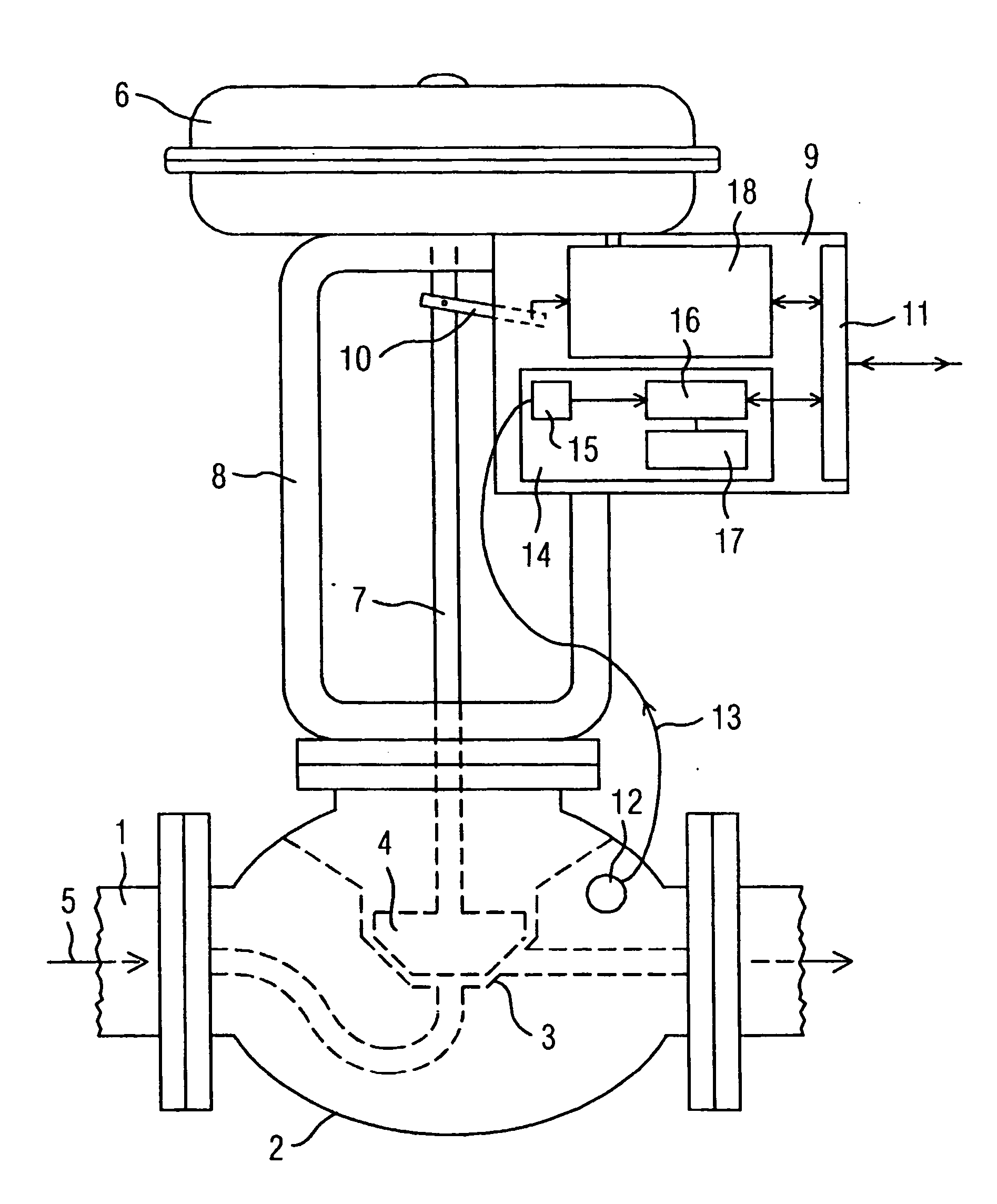
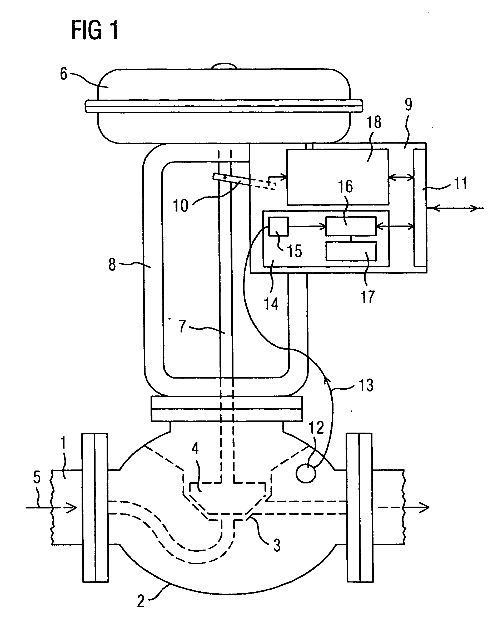
[0033] According to FIG. 1, a valve 2 is installed in a pipeline 1 of a process plant (not depicted). The valve 2 controls the flow of a medium 5 by a corresponding stroke of a closing member 4 interacting with a valve seat 3. The stroke is produced by a drive 6, for example a pneumatic drive, and is transmitted to the closing member 4 via a valve rod 7. The drive 6 is connected to the valve housing via a yoke 8. A positioner 9 with a control unit 18 is mounted to the yoke 8. The positioner 9 detects the stroke on the input side by way of a connecting element 10 that engages with the valve rod 7, compares the stroke with a setpoint value supplied via a data interface 11 of a field bus, and controls the drive 6 on the output side in terms of a correction of the control deviation. A sensor 12 for structure-borne noise is mounted to the housing of the valve 2. A signal 13 from the sensor 12 is supplied as a measurement signal to a device 14 for evaluating the measurement signal 13. In ...


PUM


Abstract

A diagnostic system, for a valve (2), having a sensor (12) that senses structure-borne noise and having a device (14) for evaluating a measurement signal (13) of the structure-borne noise. During a calibration process, a first progression of the measurement signal is sensed for the closed position of the valve (2) and a first value (w1) of a characteristic is determined. To simulate leakage noise, the valve (2) is nearly closed during operation, a second progression of the measurement signal is sensed and a second value (w2) is determined. If the deviation of the second value from the first value is sufficiently large, a diagnosis is possible. A third progression of the measurement signal is sensed for the closed position of the valve as in an installed condition, and a third value (w3) is determined. If the deviation of the third value (w3) from the first value (w1) is too great, and if a diagnosis has been identified as being possible, then the system deduces that the valve leaks.

Description

[0001] This is a Continuation of International Application PCT / DE03 / 01312, with an international filing date of Apr. 22, 2003, which was published under PCT Article 21(2) in German, and the disclosure of which is incorporated into this application by reference.FIELD AND BACKGROUND OF THE INVENTION [0002] The invention relates to a diagnostic system for a valve that can be actuated by a drive by way of a positioner and that has a sensor for detecting structure borne noise, wherein the diagnostic system determines whether diagnosis is possible and, if so, whether the valve leaks. The invention also relates to a diagnostic method, wherein the diagnostic method determines whether diagnosis of the valve is possible and, if so, whether the valve leaks. [0003] In many areas of process engineering and power engineering, the trouble-free operation of a plant depends on the flawless functioning of the control and check valves used. To avoid costly irregular operational interruptions, any valv...

Claims


Application Information

Patent Timeline
Patent Type & Authority Applications(United States)
IPC IPC(8): F16K37/00
CPCF16K37/0083Y10T137/8175Y10T137/8242
Inventor ENS, WOLFGANGPUETTMER, ALF
Owner SIEMENS AG
Why Eureka
Try Eureka