Drilling systems

Active Publication Date: 2005-06-16
CCT TECH
View PDF40 Cites 25 Cited by
  • Summary
  • Abstract
  • Description
  • Claims
  • Application Information

AI Technical Summary

Benefits of technology

[0009] Such a drilling system and such a percussion drilling assembly may have, according to certain aspects of the present invention, a driver which is a fluid motor driven by a drilling fluid passed downwardly through a drill string to the drill assembly, and wherein the drilling fluid is exhausted from the fluid motor through the second end of the housing assembly and through the drill bit. Such a drilling system and such a percussion drilling assembly may operate so that when the driver is a fluid motor it has a liquid inlet and a liquid outlet, a stator, and a rotor positioned between the liquid inlet and the liquid outlet, the driver with a rotary shaft and the rotor connected to the rotary shaft so that rotation of the rotor causes corresponding rotation of the rotary shaft to drive the fluid compressor. Such a percussion drilling assembly may also have the liquid inlet of the motor connected to an inlet passageway in the first end of the housing assembly so that liquid from a drill string flows through the inlet passageway and then flows between the stator and the rotor to the liquid outlet to effect rotation of the rotor with respect to the housing assembly, thereby rotating the rotary shaft and driving the

Problems solved by technology

High inertial loading on the contact surfaces of the endless loop grooves caused high wear, requiring frequent replacement of the complete rotary shaft section.
Roller elements that extended into the endless loop grooves required specialized profile grinding and heat treatment processes, and were also subjected to the same high inertial loading that created the need for frequent replace

Method used


Image

  • Drilling systems
  • Drilling systems
  • Drilling systems

Examples


Embodiment Construction

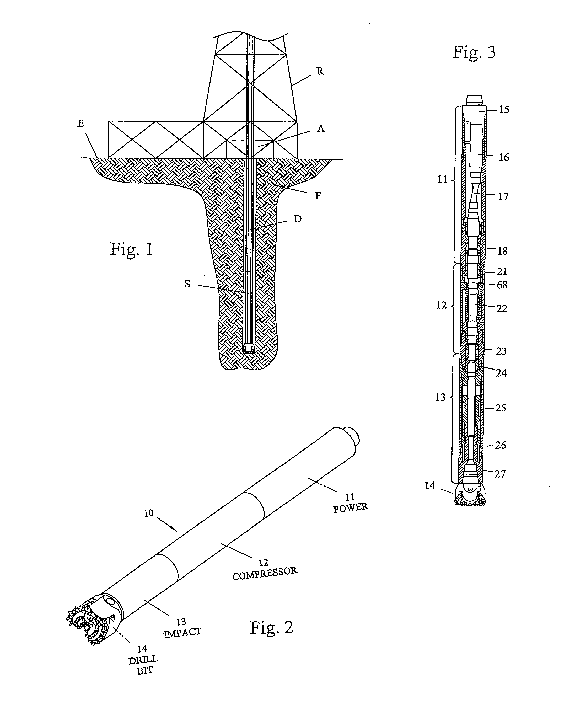
[0038] Referring now to FIG. 1, a drilling system S according to the present invention is installed at the bottom of a string of drill pipe D of a drilling apparatus A in a drilling rig R at an earth surface E. The drill pipe D extends down into an earth formation F.

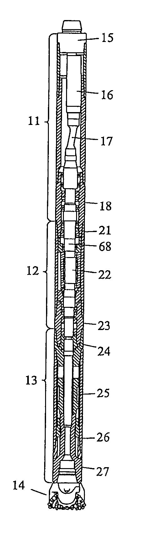
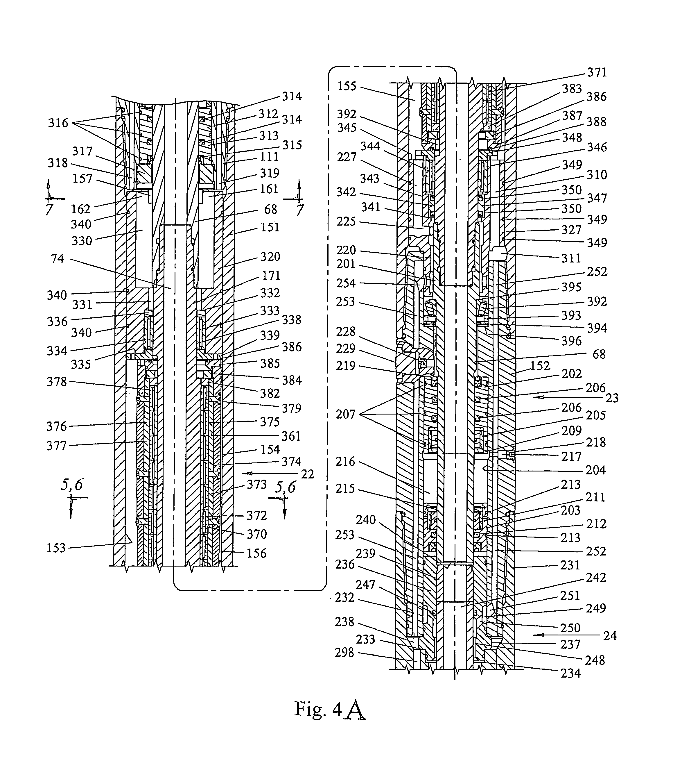
[0039] As shown in FIGS. 2 and 3, a percussion drilling assembly 10 according to the present invention has four components, or modules, connected in series: a power module 11, a compressor module 12, an impact module 13, and a drill bit 14. The power module 11 has a backhead 15, a motor segment 16, a drive shaft segment 17, and a bearing segment 18. The compressor module 12 has an anchor segment 21, an eccentric segment 22, and a connector segment 23. The impact module 13 has a fluid communication segment 24, an impact piston segment 25, a chuck 26, and a bit adapter 27.

[0040] A mud motor located in the motor segment 16 is rotated by the downwardly flowing drilling fluid or mud, supplied via a drill string of drill pip...


PUM

PropertyMeasurementUnit
Pressureaaaaaaaaaa

Abstract

The present invention discloses, in certain asp cts, systems and methods for producing cyclical impacts and, in certain aspects for moving a drilling apparatus for drilling a borehole in a formation, the system in certain embodiments including a housing with a longitudinal axis and a movable member movably disposed therein and movable within the housing transversely to the longitudinal axis of the housing and positioned within the housing with a first space on a first side thereof and a second space on a second side thereof, the movable member substantially fluidly isolating the two spaces and movable to compress gas in one of the first space and the second space while decompressing gas in the other space so that a charge of compressed gas exits from the housing to move an impact member; e.g. for impacting a pile to be driven into the earth or for impacting a drill apparatus for drilling a wellbore, the movable member movable continuously to provide a series of impacts.

Description

BACKGROUND OF THE INVENTION [0001] 1. Field of the Invention [0002] The present invention is directed to wellbore drilling systems and, in certain aspects, to such systems with a percussion drill assembly which cyclically impacts a drill bit. [0003] 2. Description of Related Art [0004] The rate of penetration of a formation by a drill bit is generally proportional to the weight, or downward thrust, placed on the drill bit. The addition of repetitive impact blows on a drill bit, e.g. those provided by a percussion drilling assembly, regardless of the weight applied to the bit, will increase the penetration rate of the drill bit. Due to the short duration of each impact blow, deviation of the borehole is minimized. Impact blows, therefore, can be used as a substitute for part of the weight on the drill bit. [0005] One typical percussion drill assembly for drilling a borehole in an earth formation is described in U.S. Pat. No. 5,662,180 issued Sep. 2, 1997 incorporated fully herein by ...

Claims


Application Information

Patent Timeline
IPC IPC(8): E21B4/06E21B4/14E21B4/20
CPCE21B4/20E21B4/06
Inventor CAMPBELL, PAUL B.COFFMAN, JAMES E.
Owner CCT TECH
Why Eureka
Try Eureka