Assembly comprised of a brake disk with a hub

a technology of brake disc and hub, which is applied in the direction of braking disc, cycle brake, cycle equipment, etc., can solve the problems of affecting assembly precision and fabrication time, and achieve the effect of convenient and cost-effective manufacturing

Inactive Publication Date: 2005-06-16
FAG KUGELGISCHER GEORG SCHAFER
View PDF11 Cites 20 Cited by
  • Summary
  • Abstract
  • Description
  • Claims
  • Application Information

AI Technical Summary

Benefits of technology

[0005] The object of the invention is therefore to provide an assembly comprised of a brake disk and a hub which is easy and cost-effective to manufacture and which also fulfills the stringent requirements in terms of compensating for thermal expansion rates.
[0006] This object is achieved by the invention which concerns an assembly comprised of at least one brake disk with a hub. Webs which are adjacent to one another in the circumferential direction extend between and are anchored to the brake disk and the hub. At least two of the webs which are adjacent to one another in the circumferential direction are formed together in one piece, either from a bent section joining them or because adjacent segments having respective adjacent webs are attached. The webs absorb stresses between the brake disk and the hub.
[0021] The brake disks are provided on the axially lateral friction faces with axial depressions which preferably extend radially over a specific width of a few millimeters and of an axial depth into the brake disk and which are directly axially adjacent to the region at which the limbs are anchored to the brake disk. As a result, deformations such as axial corrugations on the brake disk due to different thermal expansion rates of the materials which are anchored to one another are avoided.
[0022] The assembly is generally more elastic at the profile in the radial annular gap between the brake disk and the hub than the comparatively rigid structures of the hub and of the brake disk. Such an assembly makes it possible to prevent deformations on the brake disk such as “corrugations” and to compensate for thermal expansion of the brake disk in the radial and axial directions. In the radial gap, the profile is therefore at least radially elastic enough to compensate such deformations in an elastically flexible fashion, and rigid enough in the tangential or circumferential direction of the hub to transmit the braking torques via the assembly virtually without deformations.
[0023] The assembly is easy and cost-effective to manufacture. The elasticity of the webs in the annular gap can be adjusted easily and virtually to any desired extent by changing the geometry of the assembly.

Problems solved by technology

Having a large number of individual spokes which have to be inserted into the casting mold and subsequently adjusted has a disadvantageous effect on the fabrication times and on the precision of the assembly.

Method used


Image

  • Assembly comprised of a brake disk with a hub
  • Assembly comprised of a brake disk with a hub
  • Assembly comprised of a brake disk with a hub

Examples


Embodiment Construction

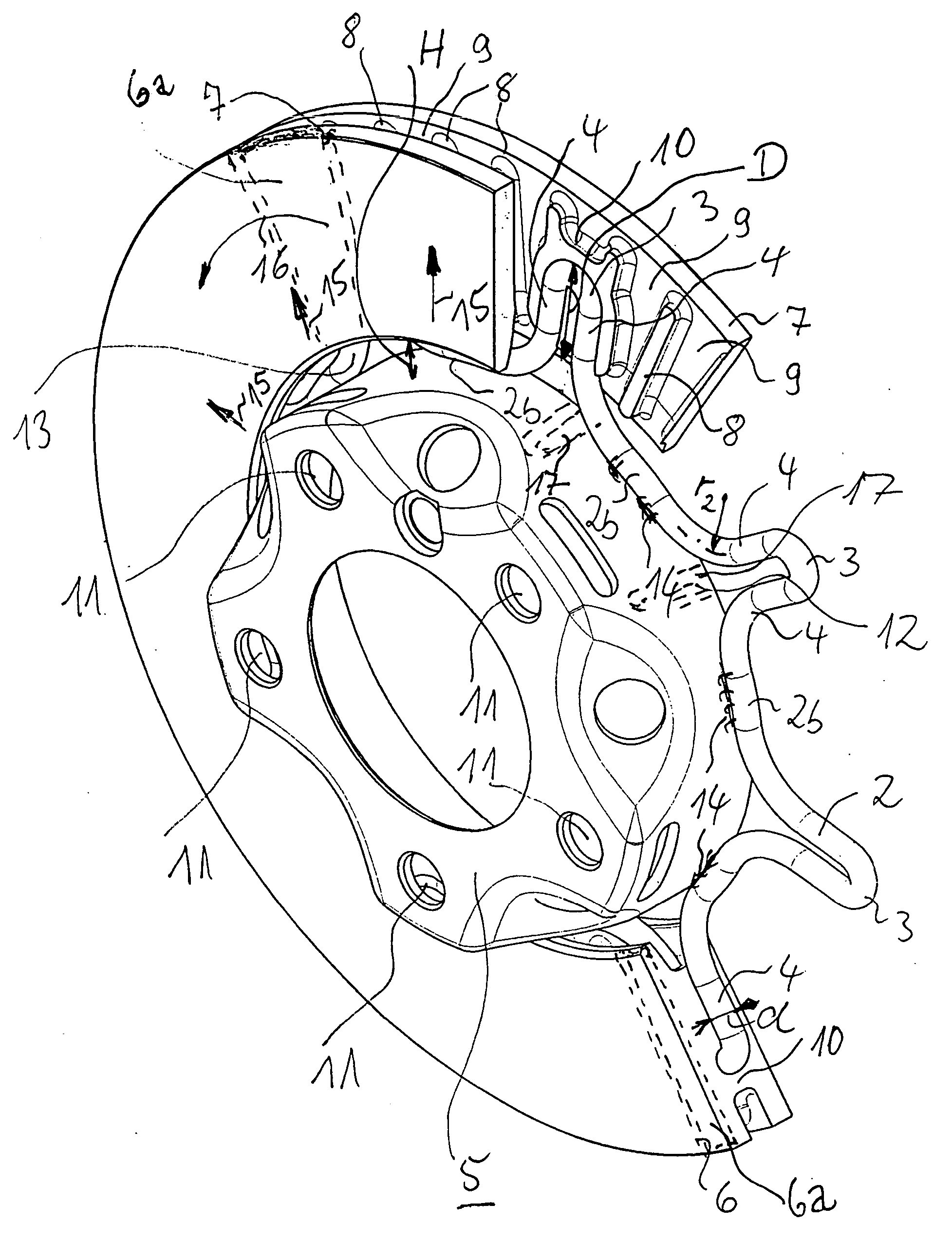
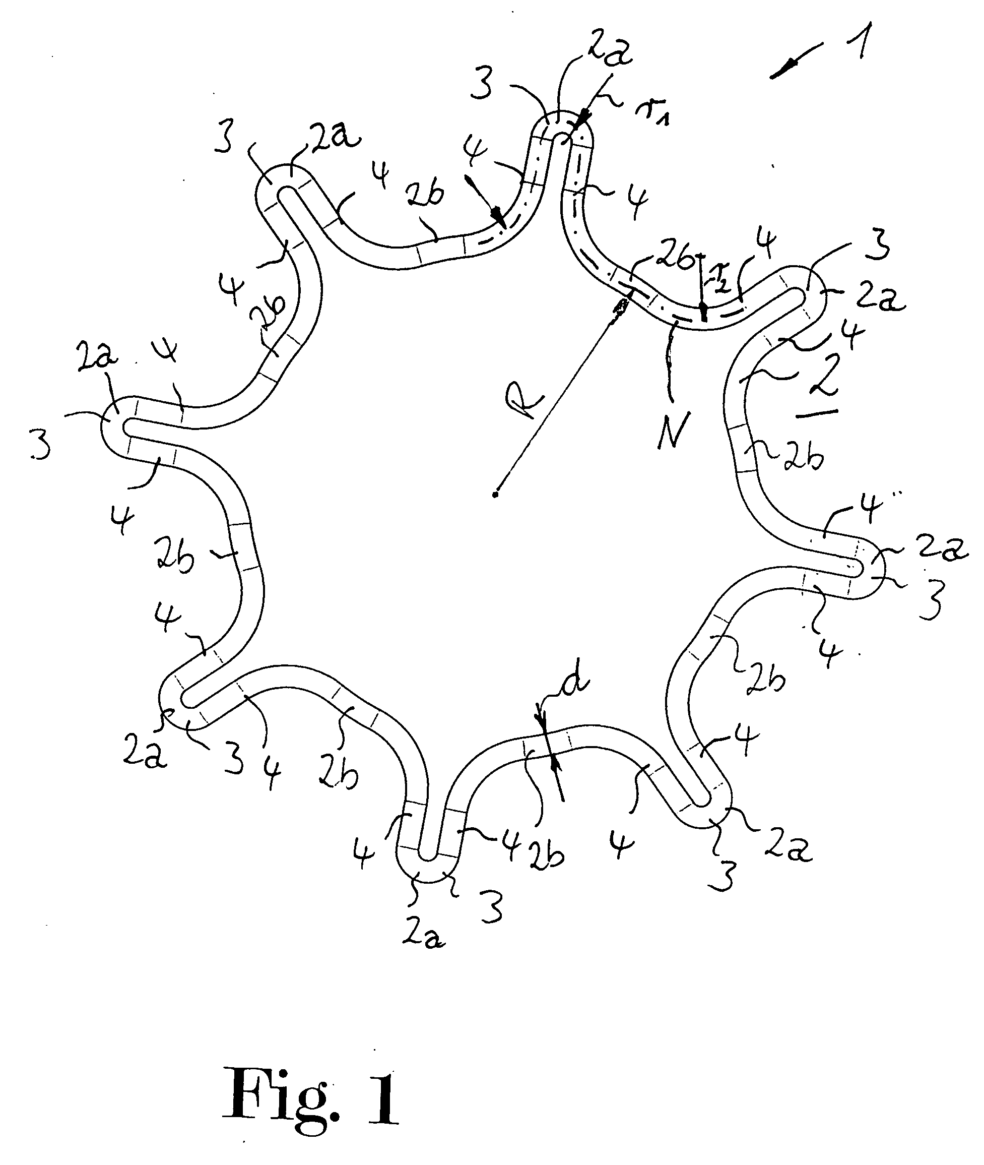
[0030] A connector element 1 shown in FIG. 1 is a continuous, generally ring shape 2 made of wire, and the ring is formed in the shape of a star. The ring 2 has a profile with a round cross section and is star shaped to define prong-like pins 3 which are directed radially outward. Each of the pins 3 is formed by two webs 4 of the ring which are directly adjacent to one another. The webs 4 merge into one another in the circumferential direction regions between the pins of the sections 2a and 2b of the ring.

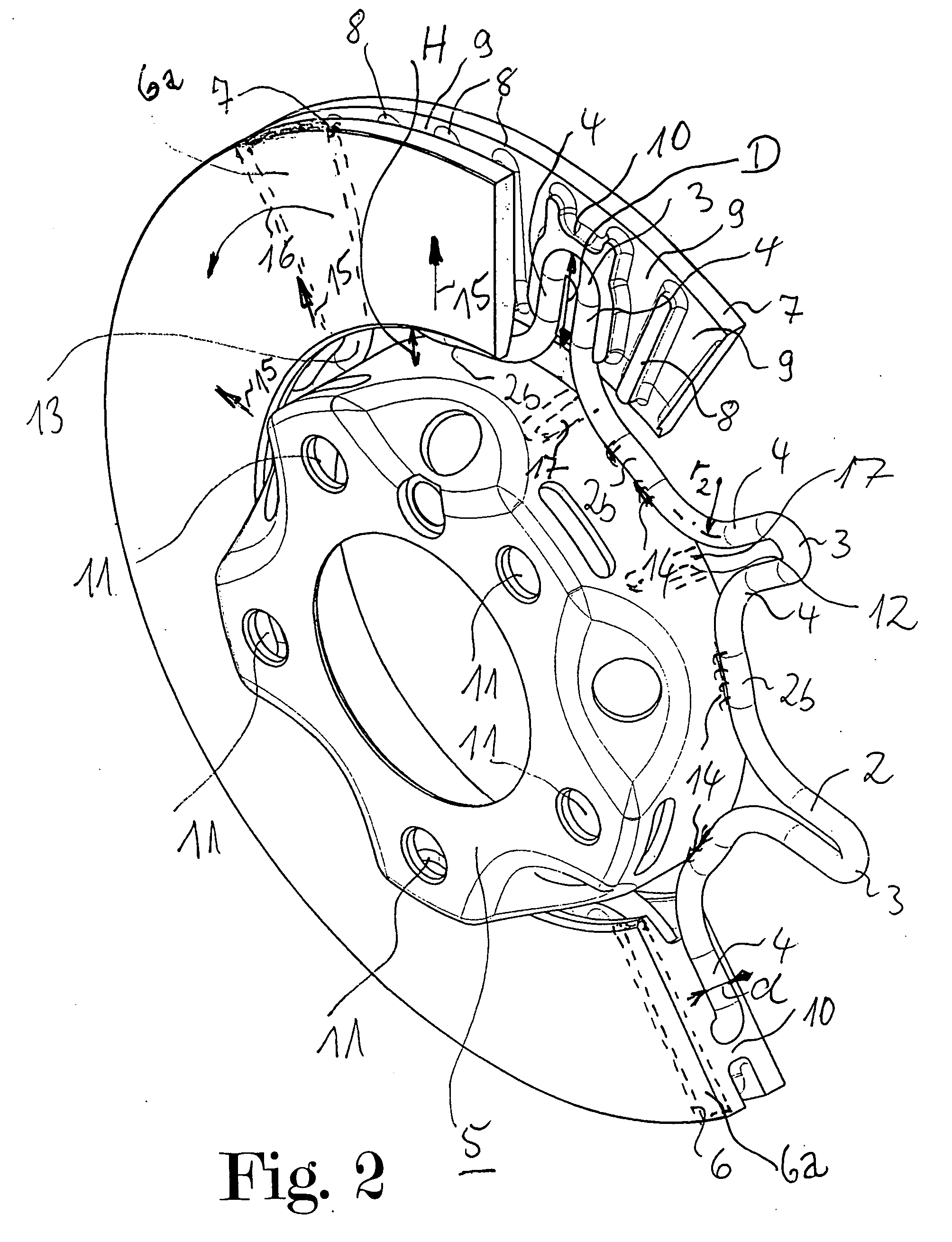
[0031] The shape of each section 2a is predefined by the bending radius r1 of the neutral bending line N. The sections 2b are firstly described by the radius R1 with respect to the bending line N. The radius R1 is the internal radius of the ring 2. The radius R1 corresponds to the external radius of the seat of the ring 2 on a hub 5 according to FIG. 2 which is formed as a brake disk chamber, plus half the diameter d of the wire. Further along section 2b in both circumferential di...


PUM


Abstract

An assembly comprised of a brake disk with a hub. Webs which are adjacent to one another in the circumferential direction extend between and are anchored to the brake disk and are attached to the hub. At least two of the webs which are adjacent to one another in the circumferential direction are formed together in one piece, either from a bent section joining the webs or because adjacent segments having respective adjacent webs are attached. The webs absorb stresses between the brake disk and the hub.

Description

FIELD OF THE INVENTION [0001] The present invention relates to an assembly comprised of at least one brake disk with a hub comprised of webs which are adjacent to one another in the circumferential direction between the brake disk and the hub, wherein the webs which are anchored to the brake disk are attached to the hub. BACKGROUND OF THE INVENTION [0002] An assembly of this type is described in AT 265359. A brake disk having a cast friction body is connected by spokes to a hub made of steel. The hubs are individual iron profiles. In order to manufacture the assembly, the spokes are first embedded in a casting mold for the friction body and are cast in order then to be welded to the outer surface of the hub. [0003] Such an assembly can be used for easily connecting brake disks and brake disk pots which are made of different materials to one another. One of the objectives in the manufacture of modern disk brakes for motor vehicles is rapid, simple and cost-effective mounting of such ...

Claims


Application Information

Patent Timeline
Patent Type & Authority Applications(United States)
IPC IPC(8): B60B27/00F16D65/02F16D65/10F16D65/12
CPCF16D65/12F16D2065/1316F16D2065/1348F16D2065/1344F16D2065/1328
Inventor DOPPLING, HORSTBURGDORF, JOCHENNIEBLING, PETERHOFMANN, HEINRICH
Owner FAG KUGELGISCHER GEORG SCHAFER
Why Eureka
Try Eureka