
Process for continuous ion exchange

a technology of countercurrent ion exchange and process, which is applied in the direction of moving filter element filter, separation process, filtration separation, etc., can solve the problem of significant amount of environmental waste generated

Active Publication Date: 2005-06-16
DE NORA WATER TECH INC
View PDF14 Cites 30 Cited by
  • Summary
  • Abstract
  • Description
  • Claims
  • Application Information

AI Technical Summary

Benefits of technology

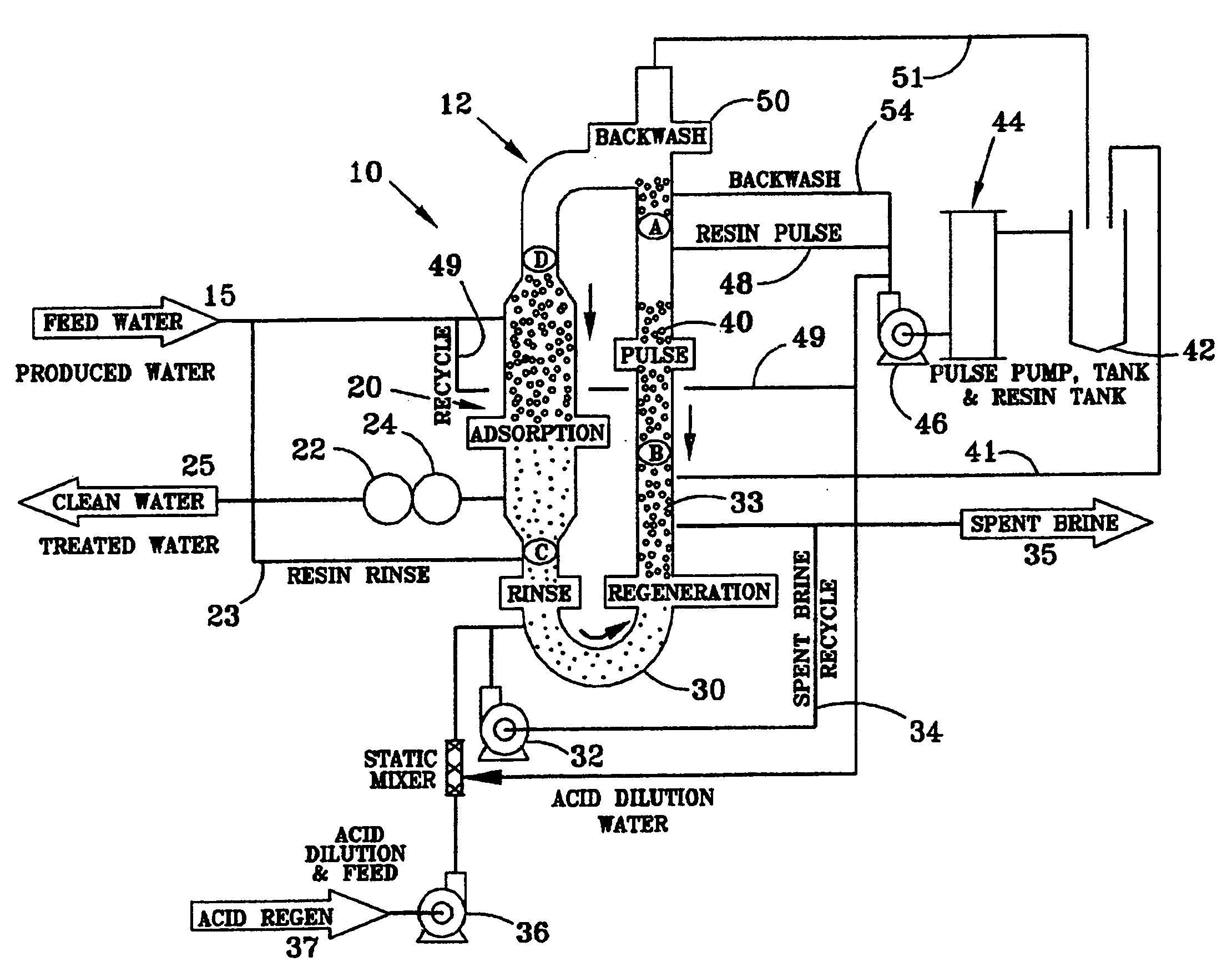
[0008] The present invention relates to the discovery of an environmentally efficient continuous countercurrent ion exchange that removes contaminants from liquid solutions, waste waters for example, while significantly reducing the waste streams resulting from the process. The process treats a contaminated feed stream using a Higgins Loop™ closed loop contactor. Advantageously, the process of this invention uses a quality measurement system that reduces the amount of acid used during the process and beneficially produces a spent brine stream that is useful in other industrial processes thereby eliminating a waste stream into the environment. An additional water waste stream is eliminated because wastewater is recycled back into the contractor during the steps of this process rather then being piped out as a waste.
[0009] The contractor comprises an adsorption area or section for treating the contaminated stream, a regeneration area comprising ion exchange resin for stripping the contaminant ions from the stream and a pulse area for advancing a resin bed. Advantageously, the ion exchange contactor of the present invention monitors the quality of the effluent treated stream after it exits the contactor and, in response to the quality measurement, advances the regenerated resin bed so that fresh resin is available within the adsorption section when needed and additional acid is not added prematurely.

Problems solved by technology

None of these references, however, teach or suggest a continuous counter current ion exchange within a closed loop that automatically adjusts resin regeneration and reduces the significant amount of environmental wastes generated by the system.

Method used


Image

  • Process for continuous ion exchange
  • Process for continuous ion exchange
  • Process for continuous ion exchange

Examples


Embodiment Construction

[0034] The process and apparatus for continuous ion exchange of the present invention is environmentally efficient in that it removes contaminants from liquid solutions, waste waters for example, while significantly reducing or eliminating the waste streams typically resulting from the process. Recycling the spent brine stream, water and acids used in the process reduces or eliminates the volume of effluent waste streams, and in some cases, turned them into useable end products.

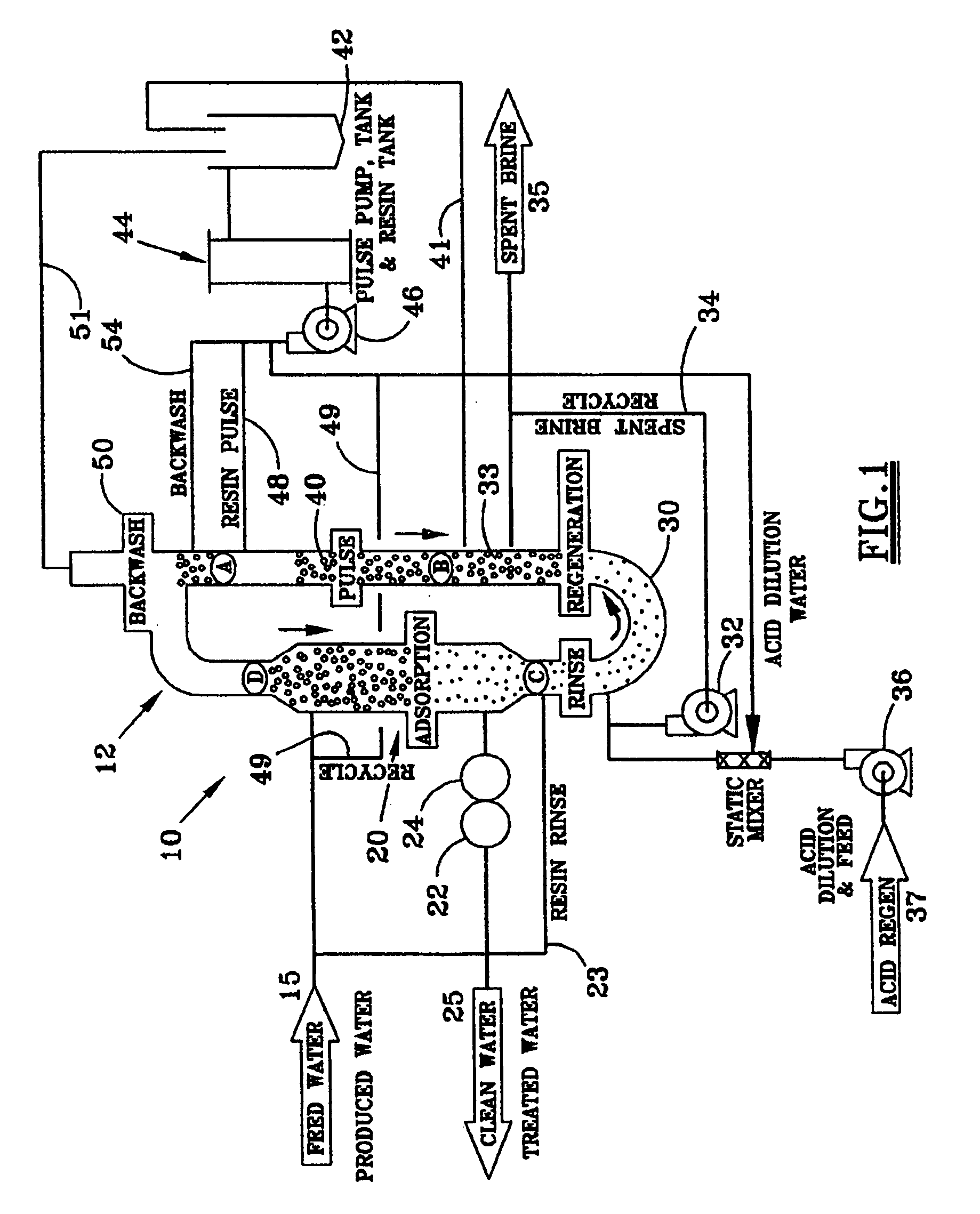
[0035] Referring to the FIG. 1, a contaminated feed stream 15 is piped to a Higgins Loop™ closed loop contactor 12. The feed stream can comprise any solution having ions that need to be removed from the solution, metals such as sodium or potassium for example, either because of environmental concerns or for purposes of concentrating the remaining ions in the stream. The various embodiments of this invention can encompass metal or ion extraction from such processes as ore leach or wastewater demineralization....


PUM

PropertyMeasurementUnit
densityaaaaaaaaaa
densityaaaaaaaaaa
adsorptionaaaaaaaaaa

Abstract

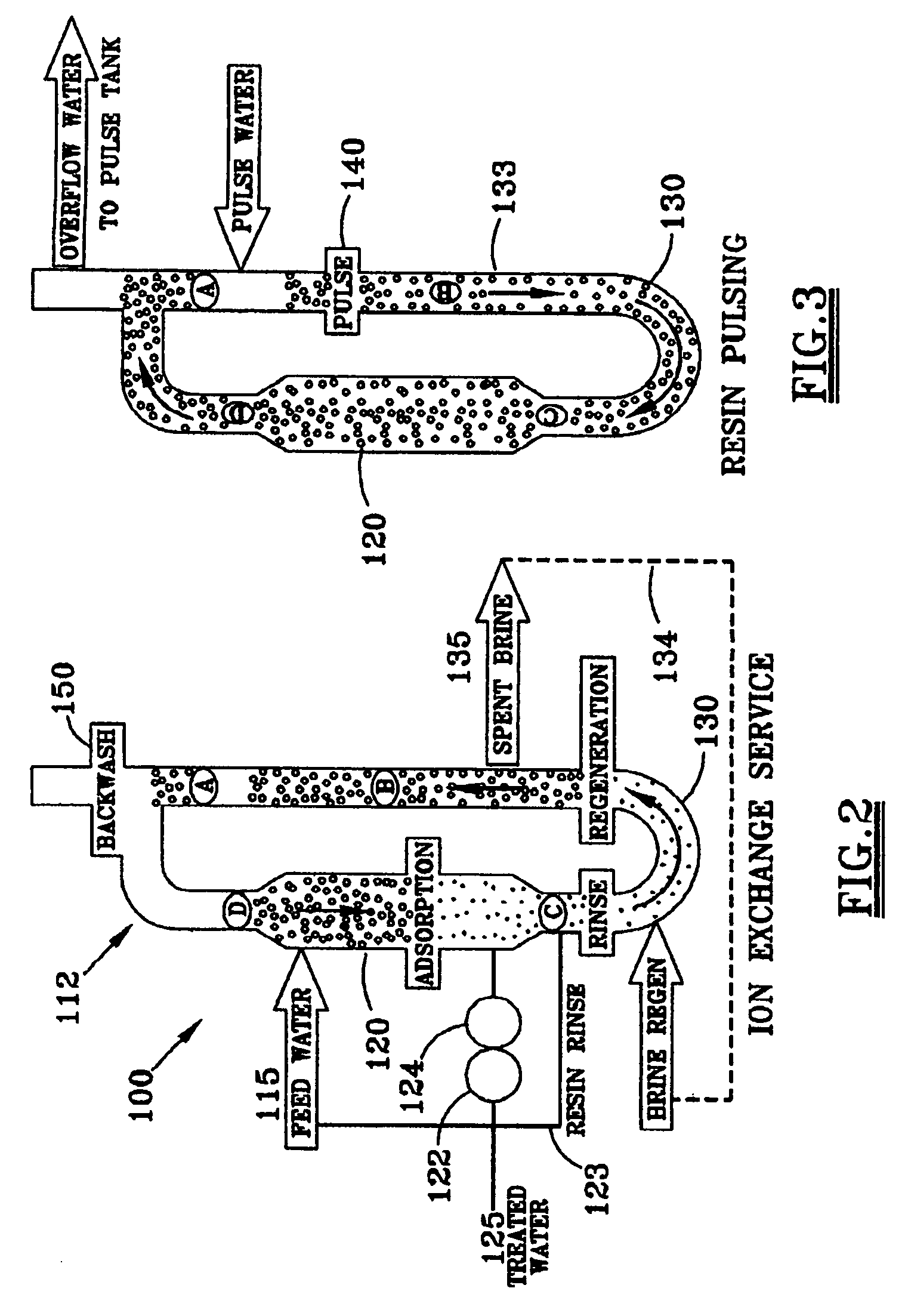
A process for continuous countercurrent ion exchange comprises piping a contaminated feed stream into a closed loop ion exchange contactor. The contactor is an ion exchange bed that has three or more reaction segments. The segments are comprised of at least an adsorption segment for treating the contaminated feed stream, a regeneration segment for stripping the contaminant ions from the resin bed, and a pulse segment for advancing the resin bed. Simultaneously, the feed stream is moved through the contactor in the same direction as the regeneration stream. Measuring the quality of this treated feed stream after it exits the contactor monitors the treatment capacity of the resin bed. In response to this quality measurement, the regenerated resin bed is advanced in the pulse segment of the contactor. The spent brine is recycled back to the contactor until the final effluent brine is highly concentrated. After the resin stops advancing, the feed stream and regeneration stream resume flow. Process water is recycled in four different steps of the ion exchange process, for the dilution of acid, as resin rinsing water, for back wash and during the resin pulsing stage.

Description

FIELD OF THE INVENTION [0001] The present invention relates to a process for continuous countercurrent ion exchange. More particularly to a process for an environmentally efficient continuous countercurrent ion exchange within a closed loop ion exchange contactor. BACKGROUND OF THE INVENTION [0002] Ion exchange methods using a closed loop system have been utilized for a variety of industrial and agricultural processes to remove unwanted anions and cations from solutions. The continuous operation of ion exchange reaction units having moving beds has been taught by I. Higgins in a multitude of patents including U.S. Pat. No. 3,194,663 for the radioactive decontamination of milk, U.S. Pat. No. 3,492,092 for an ion exchange process for treating crude mineral solutions, U.S. Pat. No. 3,579,322 for the recovery of phosphate from phosphate containing pond water, U.S. Pat. No. 3,580,842 for a downflow ion exchange, U.S. Pat. No. 3,677,937 for a split loop contactor, U.S. Pat. No. 3,775,088 ...

Claims


Application Information

Patent Timeline
Patent Type & Authority Applications(United States)
IPC IPC(8): B01J49/00C02F1/42
CPCB01J49/0034B01J49/003B01J49/12B01J49/14
Inventor DENNIS, RICHARD S.
Owner DE NORA WATER TECH INC
Learn More