Electric power unit for machining of wire electric discharge machine

a technology of electric discharge machine and electric power unit, which is applied in the field of electric power, can solve the problems of abnormal electric discharge state, inability to effectively conduct electric discharge machining, and no means of continuing electric discharge, so as to prevent the occurrence of electrolytic corrosion of workpieces, improve machining efficiency, and improve machining speed

Inactive Publication Date: 2005-06-16
MITSUBISHI ELECTRIC CORP
View PDF5 Cites 17 Cited by
  • Summary
  • Abstract
  • Description
  • Claims
  • Application Information

AI Technical Summary

Benefits of technology

[0007] The present invention has been accomplished to solve the above problems. It is an object of the present invention to provide an electric power unit for machining of a wire electric discharge machine capable of enhancing the efficiency of electric discharge machining.
[0012] Since the electric power unit for machining of a wire electric discharge machine of the present invention is composed as described above, it is possible to provide the following effects. The machining efficiency can be enhanced, and the machining speed can be enhanced. Further, it is possible to prevent the occurrence of electrolytic corrosion of a workpiece.

Problems solved by technology

Further, there is provided no means for continuing electric discharge in the case of normal electric discharge between the electrodes.
Therefore, it is impossible to conduct electric discharge machining effectively.
In the electric power unit for machining of the above conventional wire electric discharge machine, the following problems may be encountered.
This abnormal state of electric discharge occurs in the case where the wire electrode and workpiece are short-circuited to each other or in the case of concentrated electric discharge.
In the case of the occurrence of concentrated electric discharge, even if voltage is impressed upon between the electrodes, the electric potential difference is so small that an electrolytic action of the machining solution is not strong.
Accordingly, even if the electrolytic action of the machining solution is utilized, the machining speed can not be increased sufficiently high.
Further, it is difficult to early recover from the above abnormal state of electric discharge.

Method used


Image

  • Electric power unit for machining of wire electric discharge machine
  • Electric power unit for machining of wire electric discharge machine
  • Electric power unit for machining of wire electric discharge machine

Examples


embodiment 1

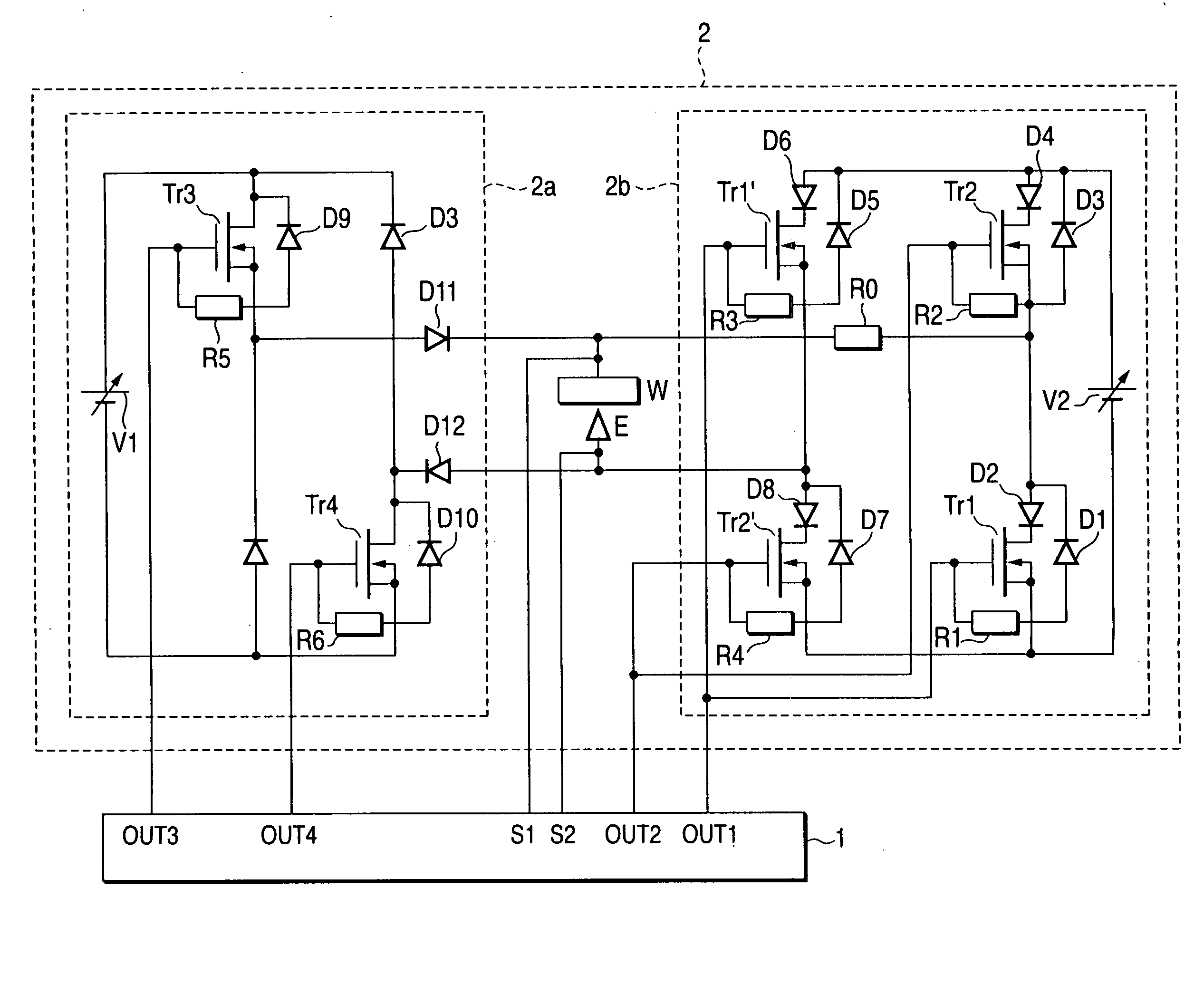
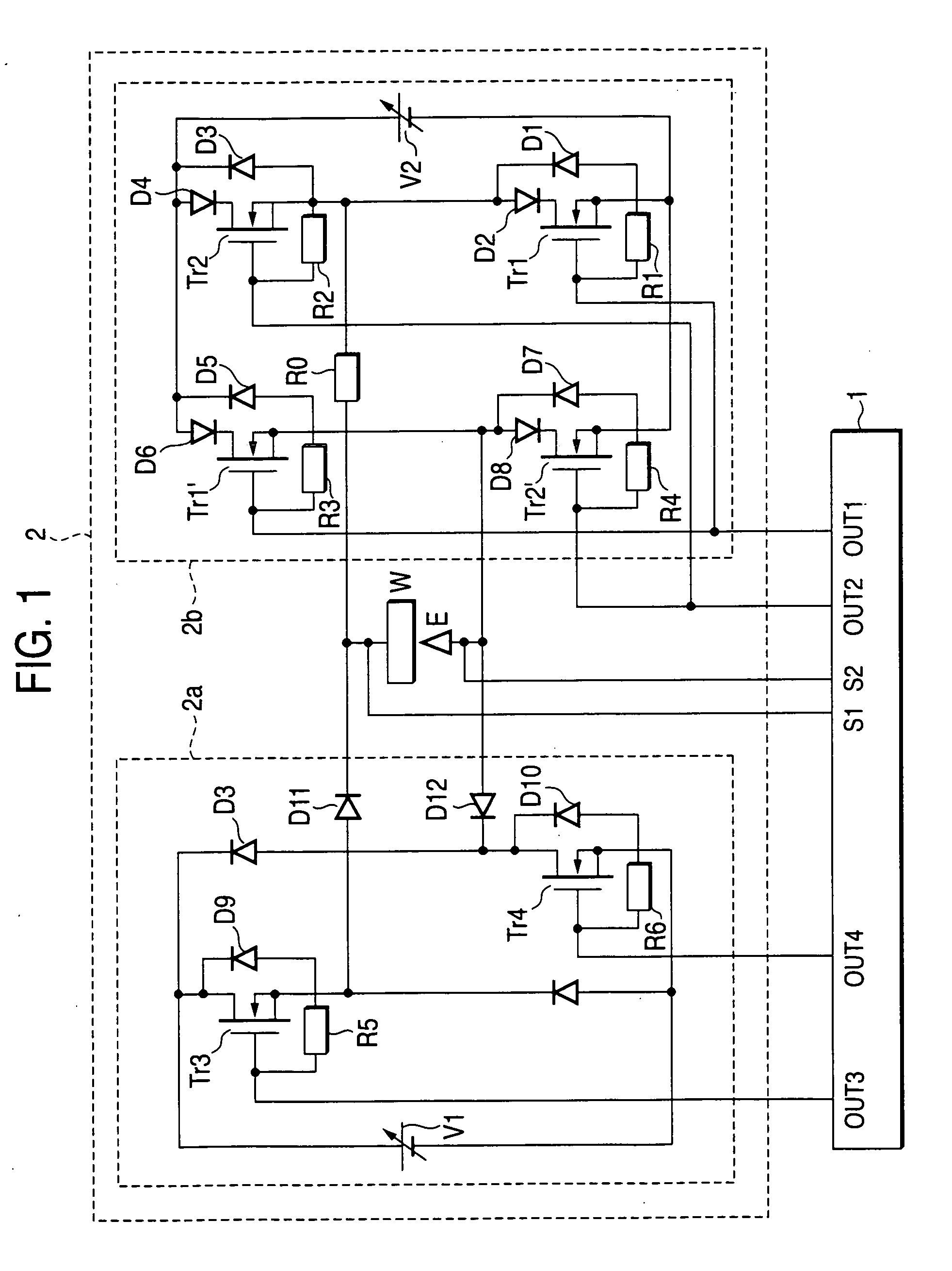
[0022]FIG. 1 is an arrangement view showing an electric power unit for machining of a wire electric discharge machine of Embodiment 1 of the present invention. In the drawing, reference numeral 1 is a machining electric power unit control circuit, reference numeral 2 is an electric power unit for machining, reference numeral 2a is a main electric discharge circuit, reference numeral 2b is an electric discharge inductive circuit, reference marks Tr1 and Tr1′ are switching elements turned on and off by drive signal OUT1 output from the machining electric power unit control circuit 1, reference marks Tr2 and Tr2′ are switching elements turned on and off by drive signal OUT2 output from the machining electric power unit control circuit 1, reference mark Tr3 is a switching element turned on and off by drive signal OUT3 output from the machining electric power unit control circuit 1, reference mark Tr4 is a switching element turned on and off by drive signal OUT4 output from the machining...

embodiment 2

[0043]FIG. 9 is an arrangement view showing a machining electric power unit control circuit 1 of controlling an electric power unit for machining of a wire electric discharge machine of Embodiment 2 of the present invention. Like reference characters are used to indicate like parts in FIG. 2 showing Embodiment 1 and FIG. 9 showing Embodiment 2. In FIG. 9, reference numeral 1c is a detection circuit for detecting an average voltage between electrodes.

[0044] The machining electric power control unit 1 includes a detection circuit 1c for detecting an average voltage between electrodes. The maximum time of electric discharge inductive voltage impression is controlled according to an output signal sent from the detection unit 1c for detecting an average voltage between electrodes. For example, in the case where the average voltage between electrodes is biased toward the positive side, the detection circuit 1c for detecting an average voltage between electrodes outputs “High”, and in the...


PUM

PropertyMeasurementUnit
clock frequencyaaaaaaaaaa
inductive voltageaaaaaaaaaa
electric discharge stateaaaaaaaaaa

Abstract

An electric power unit for machining of a wire electric discharge machine for machining a workpiece (W) in which an electric discharge inductive pulse voltage is impressed upon between electrodes of a wire electrode (E) and workpiece (W), after insulation between the electrodes has been broken by the pulse voltage and electric discharge has been induced, a pulse voltage for machining is impressed upon between the electrodes so as to conduct machining on the workpiece (W). The electric power unit for machining of a wire electric discharge machine includes an electric discharge state discriminating means (1a) for discriminating a state of electric discharge generated between the electrodes and an impression voltage selecting means (1b) for inverting the polarity of the electric discharge inductive pulse voltage from the previous electric discharge inductive pulse voltage when an electric discharge state between the electrodes is discriminated to be abnormal (Y1) or open (Y3) by the electric discharge state discriminating means (1a) and for making the polarity of the electric discharge inductive pulse voltage to be the same as the polarity of the previous electric discharge inductive pulse voltage when the electric discharge state between the electrodes is discriminated to be normal (Y2) by the electric discharge state discriminating means. Thus the machining efficiency is improved.

Description

TECHNICAL FIELD [0001] The present invention relates to improvements in an electric power unit for machining used for a wire electric discharge machine to conduct machining on a workpiece by electric discharge generated between a wire electrode and workpiece. BACKGROUND ART [0002] In wire electric discharge machining, an insulating machining solution is interposed between a wire electrode and workpiece. While the wire electrode and workpiece are being moved relatively with each other, electric power for machining is supplied from an electric power unit for machining to between the wire electrode and workpiece, so that the workpiece is machined by electric discharge energy. [0003] Electric power units of the above conventional wire electric discharge machine used for wire electric discharge machining are disclosed, for example, in Japanese Unexamined Patent Publication Nos. 8-1438, 8-300222, 9-183019 and 7-290317. In the above electric power units for machining of the conventional wi...

Claims


Application Information

Patent Timeline
Patent Type & Authority Applications(United States)
IPC IPC(8): B23H1/02B23H7/04
CPCB23H7/04B23H1/022B23H1/02
Inventor KOBAYASHI, HIROATSUMAGARA, TAKUJI
Owner MITSUBISHI ELECTRIC CORP
Why Eureka
Try Eureka