Waveguide

a waveguide and waveguide technology, applied in the field of waveguides, can solve the problems of high attenuation, not well suited to volume production, waveguide devices with moving parts, etc., and achieve the effect of preventing the leakage of energy from the waveguid

Inactive Publication Date: 2005-06-16
ERA PATENTS
View PDF4 Cites 66 Cited by
  • Summary
  • Abstract
  • Description
  • Claims
  • Application Information

AI Technical Summary

Benefits of technology

[0004] Such split constructions allow multilevel beamformers to be realised by fabrication of individual parts that are subsequently bonded together in such a way that the impact of the joint is minimised. In the case of metallic waveguides this sometimes involves dip brazing, or in the case of metallised plastics, limits the joint's position along the centre of the broadwall, in the case of rectangular waveguides. Such restrictions do not apply to dip brazed components, however these are not well suited to volume manufacture.
[0040] Accordingly, the waveguide may have two parallel metallic plates and a periodic structure of metal posts connected to one or other of the plates, without simultaneous physical contact to both. At some frequencies, the periodic structure creates a virtual short circuit between the parallel plates, preventing the leakage of energy from the waveguide. Structures including waveguides, beamformers and rotary or rotating joints can be built utilising the invention.

Problems solved by technology

However, it is very well known that slits in the narrow walls of rectangular waveguides lead to high attenuation due to the large currents flowing across the slit discontinuity.
Such restrictions do not apply to dip brazed components, however these are not well suited to volume manufacture.
Waveguide devices with moving parts (for example, rotary joints for radar antennas, phased arrays, radio frequency switches, reconfigurable filters and phase shifters) are difficult to implement since waveguides are usually based on closed metal cavities.
There is therefore a constraint imposed on the implementation of mechanically actuated phase shifting devices based on waveguides because metal or dielectric parts, including the actuator, have to be mounted inside the waveguide thereby introducing losses and distortion and requiring-a relatively complex design.
A major obstacle to the use of electrically controlled phase shifters in many scanning beam antenna applications is the high cost and the large number of phase shifting devices required for beam steering.
The production cost of electronically scanned antennas is still very high, even when significant volumes are produced.
In addition, electronic phase shifters introduce additional losses and a considerable DC power consumption that limits their application for systems that use batteries for power supply such as mobile / personal communication devices.
The implementation of these electromechanical techniques for high frequencies (typically Ku-Band, Ka-Band and millimetre wavelengths) in waveguide structures is much more difficult; in particular because high frequency waveguides are formed by a solid metal enclosure which becomes lossy when filled with dielectrics.
One possible way to realise an electro-mechanical phase shifter is to use a secondary movable wall inside a metal waveguide as disclosed in U.S. Pat. No. 3,789,330, however, this approach is difficult to realise since the secondary wall cannot be connected to the waveguide if it is to be freely movable.
This can result in the generation of spurious and additional waveguide modes which are very difficult to control.
Another issue is the placement of the control device.
If the device is placed inside the waveguide (i.e a piezoelectric crystal), it can produce severe distortion of the waveguide modes and introduce large losses.
If the device is outside the waveguide, such as for example in the abovementioned FR-A-2581255, the metal enclosure must be perforated to allow access to the moving part thereby introducing additional distortion and losses.
Despite its potential, these waveguide configurations using periodic structures do not overcome the manufacturing problems associated with contact between moving waveguide parts and they do. not allow moving parts within the structure to implement mechanical phase shifters, rotary joints and other reconfigurable devices for radio circuits.

Method used


Image

  • Waveguide
  • Waveguide
  • Waveguide

Examples


Embodiment Construction

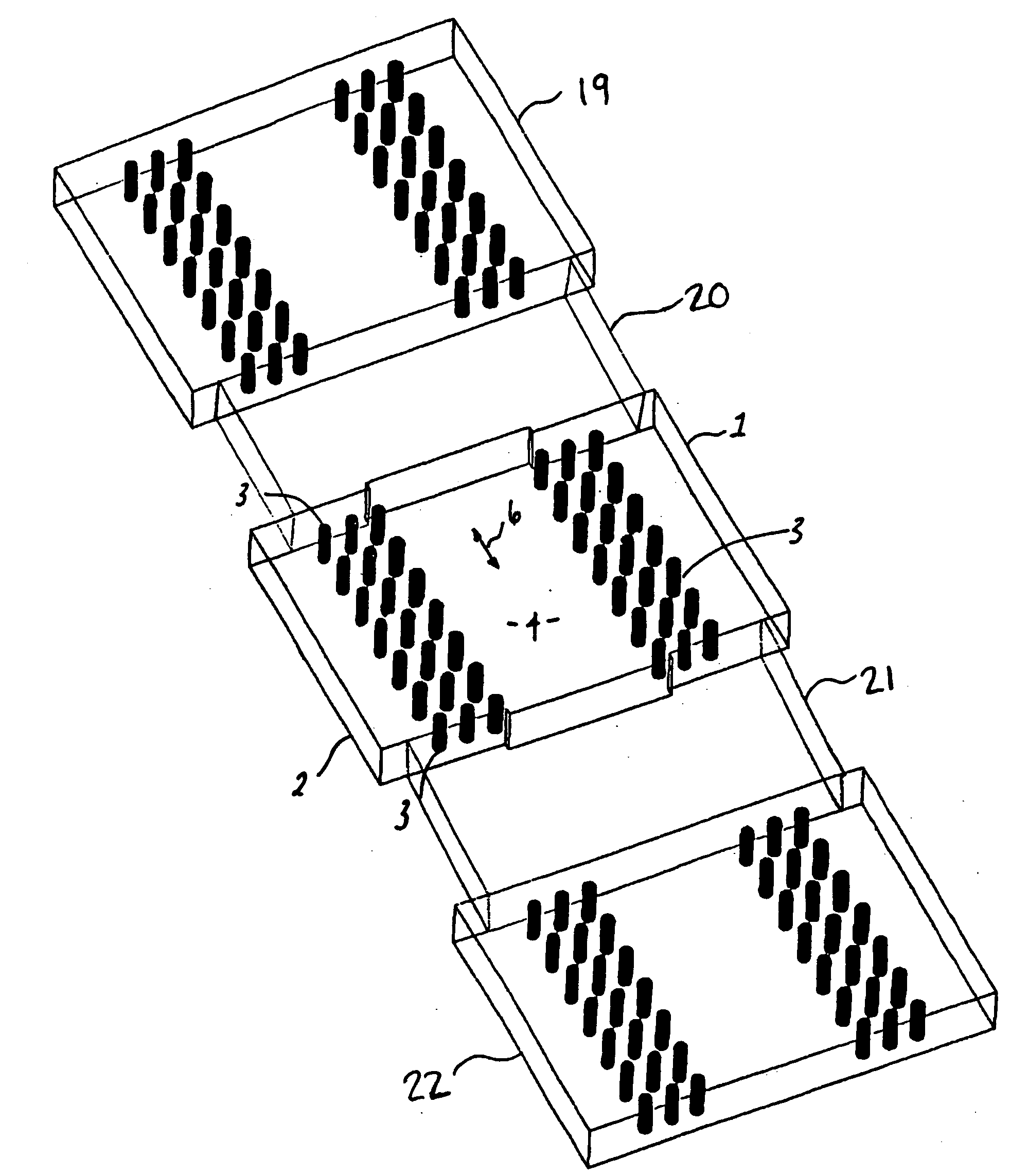
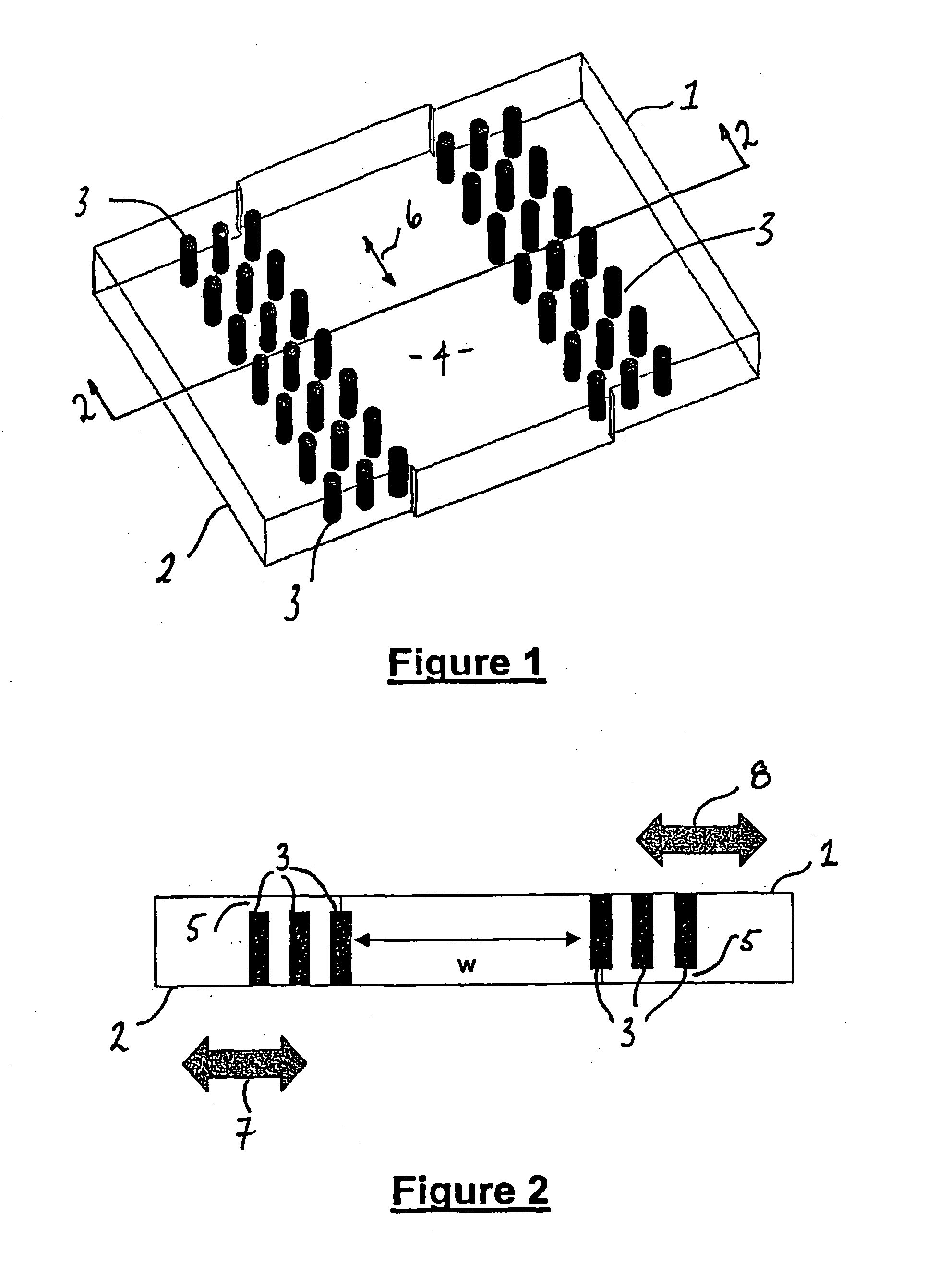
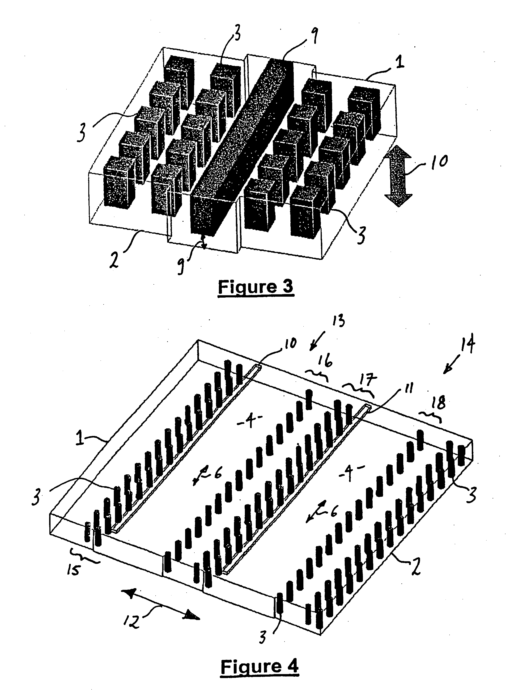
[0048] With reference to the drawings and in particular FIGS. 1 and 2, a waveguide is shown which includes two electrically conductive plates forming top 1 and bottom 2 ground planes. The ground planes 1,2 are arranged substantially parallel to each other and separated by a series of conductive posts 3. The conductive posts 3 are arranged substantially perpendicular to both of the ground planes 1,2. Ground planes 1,2 and posts 3 may, for example, be metallic or may be made from a metallised plastics material.

[0049] The posts 3 are typically distributed periodically in straight lines in one or more rows on either side of a central, guided wave region 4 which is free of posts and in which electromagnetic energy is guided and confined. The spacing of adjacent posts in a row is not necessarily constant, the distance between adjacent parallel rows is not necessarily the same and the spacing of posts in different rows is also not necessarily the same. However, it is preferred that the po...


PUM


Abstract

A waveguide structure including two parallels electrically conducting ground planes (1,2), each of which includes at least one row of spaced apart electrically conducting posts (3). The rows of posts are arranged substantially parallel to one another and the space bounded by the plates and posts defines a guided wave region (4) along which electromagnetic radiation may propagate. The posts are connected to only one of the planes so that there is no physical connection between the two ground planes (1,2). Actuating means may be connected to one or both of the ground planes to cause relative movement there between to thereby alter the electrical response of the waveguide. The direction of the relative movement may such that the distance between the rows of posts (3) is changed and / or the distance between the ground planes (1,2) is changed. Various device may utilize the described waveguide construction, including reconfigurable waveguide filters and antenna structures e.g. slotted waveguide arrays.

Description

INTRODUCTION [0001] This invention relates to waveguides and in particular, though not solely, to waveguides which include mechanically movable parts to alter their electrical characteristics. [0002] Transmission lines,. and in particular waveguides, have many applications in the microwave field including radiofrequency beamformers, filters, rotary joints and phase shifters. The use of low cost manufacturing techniques, including the use of metallised plastics for the implementation of multilevel beamforming architectures have been described in, for example, EP-A-1148583. Such structures generally require that the metallised plastics waveguide parts are slit, ideally along the centre of the broadwall (E-plane) in the case of rectangular waveguides. [0003] However, it is very well known that slits in the narrow walls of rectangular waveguides lead to high attenuation due to the large currents flowing across the slit discontinuity. [0004] Such split constructions allow multilevel beam...

Claims


Application Information

Patent Timeline
Patent Type & Authority Applications(United States)
IPC IPC(8): H01P3/12H01Q3/04H01Q3/44H01Q21/00
CPCH01P1/2005H01P3/121H01Q21/005H01Q3/443H01Q3/04H01P3/123
Inventor SANCHEZ, FRANCISCO JAVIER VAZQUEZPEARSON, ROBERT A
Owner ERA PATENTS
Why Eureka
Try Eureka