Horizontal polarized wave non-directional array antenna

a non-directional array and polarized wave technology, applied in the direction of individual energised antenna arrays, resonant antennas, particular array feeding systems, etc., can solve the problems of inability to maintain the mechanical strength of forming an array, increase the fabrication cost, and excessively simple structur

Inactive Publication Date: 2005-06-16
HARADA IND CO LTD
View PDF2 Cites 5 Cited by
  • Summary
  • Abstract
  • Description
  • Claims
  • Application Information

AI Technical Summary

Benefits of technology

[0018] Further, according to the invention, matching between the dipole antenna which is an antenna element and input / output cables is easy to carry out and the non-directionality is easy to achieve.

Problems solved by technology

However, when array antenna formation is conceived for high gain formation, there is brought about a drawback that any of horizontal polarized wave non-directional antennas including one disclosed in JP-A-11-340733, mentioned above, is complicated and fabrication cost is increased, or the structure is conversely excessively simple and a mechanical strength in forming an array cannot be maintained.

Method used


Image

  • Horizontal polarized wave non-directional array antenna
  • Horizontal polarized wave non-directional array antenna
  • Horizontal polarized wave non-directional array antenna

Examples


Embodiment Construction

[0030] An explanation will be given of an embodiment when the invention is applied to a base station antenna of PHS using a radio wave of 1.9 [GHz] band in reference to the drawings as follows.

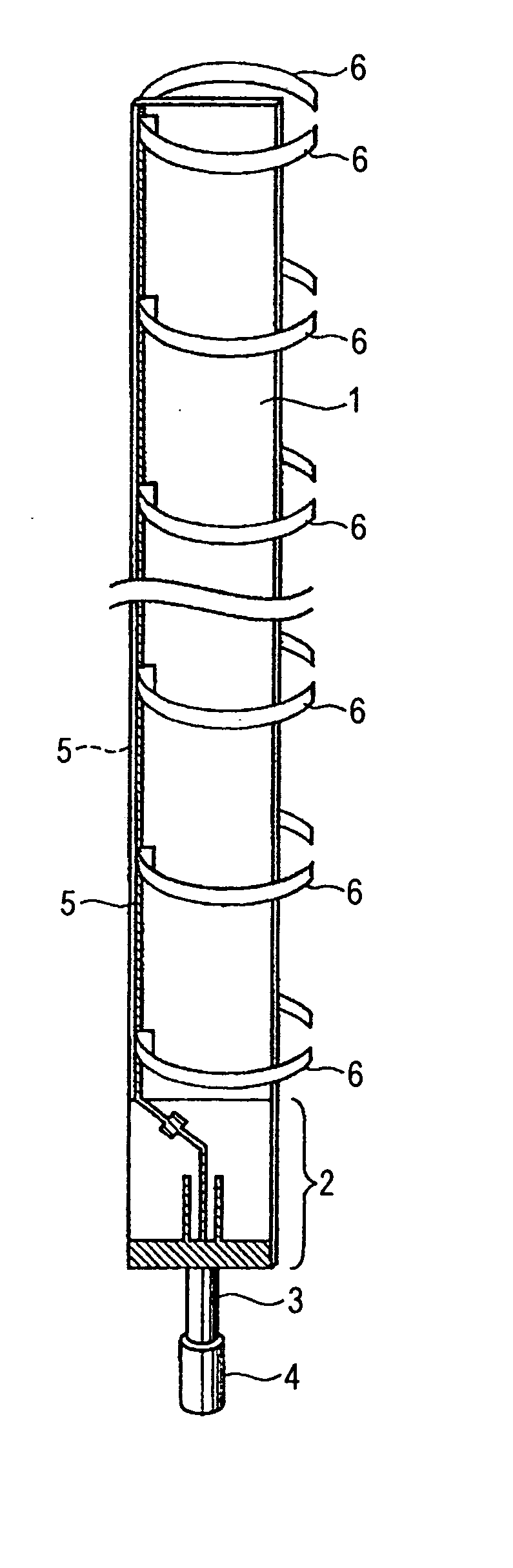
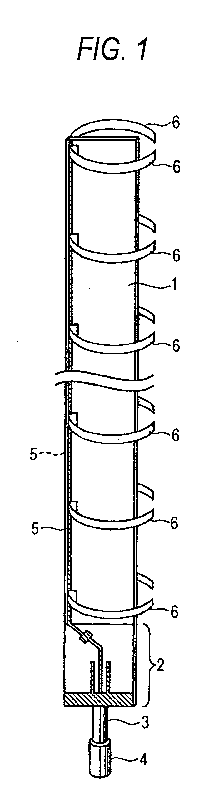
[0031]FIG. 1 shows a basic structure of antenna in which a radome is removed. In the drawing, numeral 1 designates an antenna board in a shape of a rectangular plate a direction of a long side thereof is vertically supported. The antenna board 1 is made of, for example, PPE (PolyPhenylene Ether) (dielectric constant about 3.3), fluororesin of teflon (R) (dielectric constant about 2.3) or the like. The antenna board 1 has a feeding base being provided with a balance / unbalance converting portion 2, and connected to a feeder 3 formed by a coaxial cable and including a connector 4 at a front end thereof.

[0032] The balance / unbalance converting portion 2 serves also as a matching circuit by, for example, balun. A pair of feeder lines 5, 5 that are parallel with each other are formed respectively o...


PUM


Abstract

A horizontal polarized wave non-directional array antenna, including: an antenna supporting member supported so that an axial direction thereof corresponds to a vertical direction, the antenna supporting member including a pair of feeder lines that are disposed parallel to each other in the axial direction, the antenna supporting member having abase portion; a plurality of dipole antennas arrayed along and connected to the pair of feeder lines; and a balance/unbalance converting portion formed on a feeding side of the base portion for feeding the pair of feeder lines in series.

Description

BACKGROUND OF THE INVENTION [0001] 1. Field of the Invention [0002] The present invention relates to a horizontal polarized wave non-directional array antenna particularly preferable for a base station of a mobile communication system or the like. [0003] 2. Background Art [0004] In a background art, there are variously conceived antenna apparatus used at abase station of a mobile communication system of a portable telephone, PHS (personal handy phone system: second generation codeless telephone system) or the like achieving non-directionality in a horizontal face of a horizontal polarized wave. (See, for example, JP-A-11-340733). SUMMARY OF THE INVENTION [0005] However, when array antenna formation is conceived for high gain formation, there is brought about a drawback that any of horizontal polarized wave non-directional antennas including one disclosed in JP-A-11-340733, mentioned above, is complicated and fabrication cost is increased, or the structure is conversely excessively s...

Claims


Application Information

Patent Timeline
Patent Type & Authority Applications(United States)
IPC IPC(8): H01Q21/08H01Q9/16H01Q9/44H01Q11/04H01Q21/00
CPCH01Q21/0006H01Q11/04H01Q1/42H01Q9/27
Inventor TAIRA, RYUICHIUCHINO, SHIGERUKAWASAKI, MORIYOSHI
Owner HARADA IND CO LTD
Why Eureka
Try Eureka