Polarization controlling elements

a technology of controlling elements and polarizing elements, applied in the direction of polarising elements, instruments, optics, etc., can solve the problems of limiting the contrast of the projection system, dark state light leakage onto the screen,

Active Publication Date: 2005-06-16
VIAVI SOLUTIONS INC
View PDF10 Cites 31 Cited by
  • Summary
  • Abstract
  • Description
  • Claims
  • Application Information

AI Technical Summary

Benefits of technology

[0017] a first cured photo-polymerizable liquid crystal polymer (LCP) layer having a relatively low in-pl

Problems solved by technology

Thus, the linearly polarized light that illuminates the micro-display is slightly elliptically polarized upon reflect

Method used


Image

  • Polarization controlling elements
  • Polarization controlling elements
  • Polarization controlling elements

Examples


Embodiment Construction

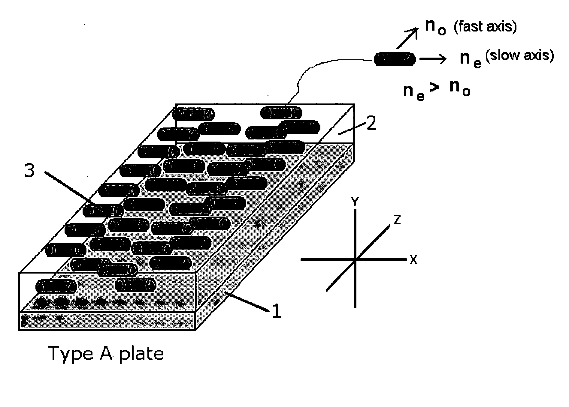
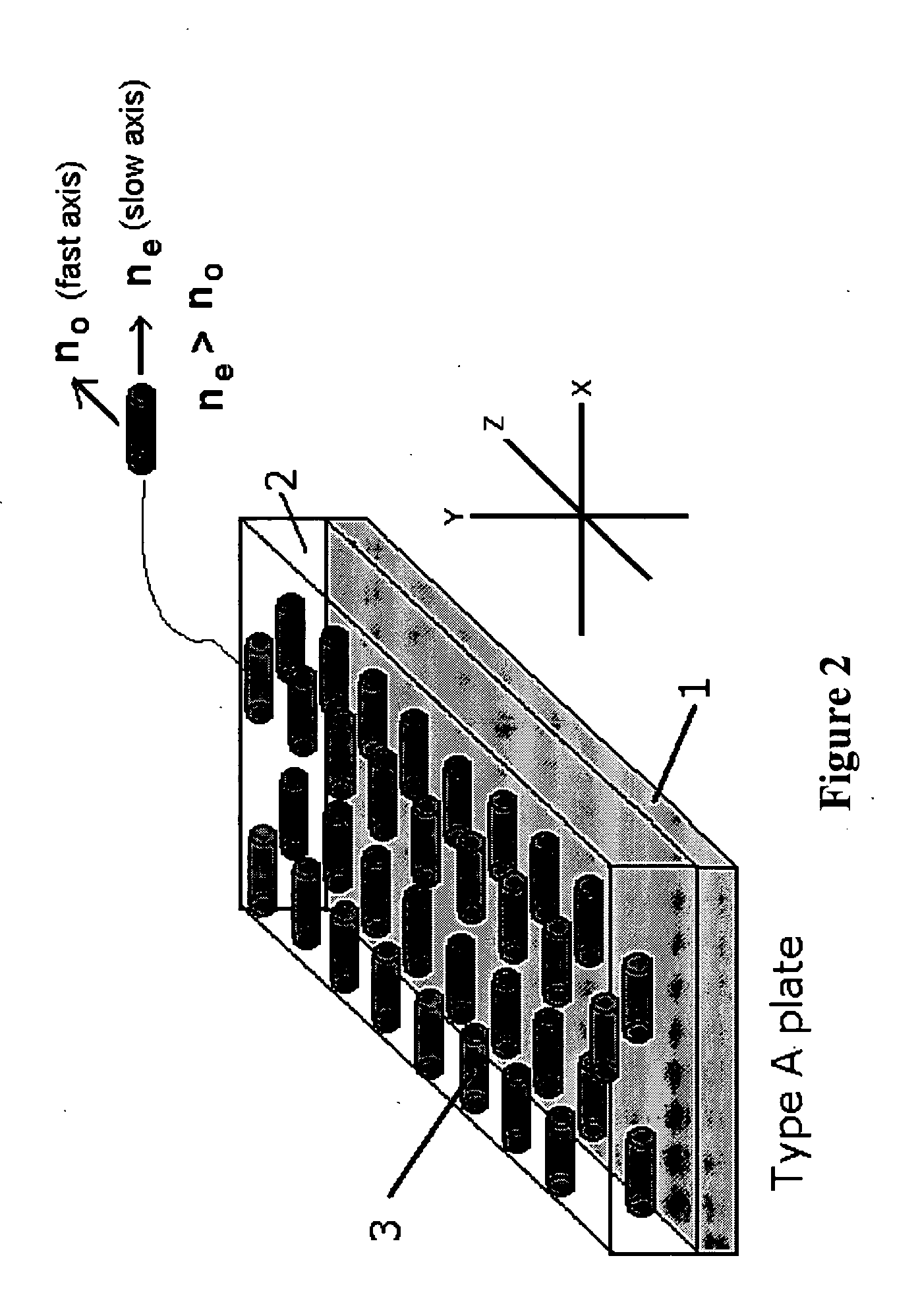
[0045] With reference to FIGS. 2 and 3, a linearly photo-polymerizable polymer layer 1 (LPP) is used to orient a photo-polymerizable liquid crystal polymer (LCP) film 2 by first, coating a transparent low-birefringence substrate 5 with a thin layer of the LPP 1. The substrate 5 can be a silica-based glass, a silica based ceramic, sapphire, polycarbonate, polyester, polychlortrifluoroethylene or polycyclic olefins, and typically has an index of refraction of between 1.35 and 2.7 @ 589 nm. Typically, a cured LCP layer has indices of refraction between 1.43 and 1.75 measured at @ 589 nm. The LPP layer 1 can be coated using any suitable method, including spin coated, dip coated, curtain coated or meniscus coated aligning. The LPP layer 1 is then heated to evaporate solvent, and exposed to linearly polarized ultra-violet light to cross-link the LPP layer 1 with the desired molecular orientation. The LCP layer 2 is coated on the photo aligned LPP layer 1 using one of the aforementioned su...


PUM


Abstract

The invention relates to a polarization compensating element (PCE) for a liquid crystal, e.g. liquid crystal on silicon (LCoS), display system manufactured using a linearly photo-polymerizable polymer (LPP) for orienting a photo-polymerizable liquid crystal polymer (LCP) film. To decrease the reflection, polarization conversion, and interference events in an LPP/LCP assembly the ΔN birefringence value of the LCP material is minimized. Dielectric coatings are added at various locations throughout the assembly for minimizing the amount of reflection, polarization conversion, and interference effects and for suppressing spatial retardance ripples.

Description

CROSS-REFERENCE TO RELATED APPLICATIONS [0001] The present invention claims priority from U.S. Patent Applications Nos. 60 / 529,315 filed Dec. 11, 2003; 60 / 587,924 filed Jul. 14, 2004; and 60 / 589,167 filed Jul. 19, 2004, which are incorporated herein by reference.TECHNICAL FIELD [0002] The present invention relates to a polarization controlling element (PCE) for liquid crystal display systems, and in particular to a trim retarder PCE, which uses a linearly photo-polymerizable polymer (LPP) to orient a photo-polymerizable liquid crystal polymer (LCP) film for increasing contrast of a liquid crystal on silicon (LCoS) micro-display based projection display system BACKGROUND OF THE INVENTION [0003] With reference to FIG. 1, a conventional LCoS projection system includes a light source 6 for generating a high power beam of light, and a polarization conversion light pipe (PCLP) 7 for ensuring substantially all of the light is linearly polarized, e.g. horizontally polarized. A first lensing...

Claims


Application Information

Patent Timeline
IPC IPC(8): G02B5/30G02F1/1335G02F1/13363
CPCG02B5/3016G02F2201/38G02F1/133634G02B5/3083
Inventor ZIEBA, JERRYMAYER, THOMASSHEMO, DAVID M.DUELLI, MARKUSTAN, KIM LEONGHENDRIX, KAREN DENISE
Owner VIAVI SOLUTIONS INC
Why Eureka
Try Eureka