
Trim retarders incorporating negative birefringence

a retarder and negative birefringence technology, applied in the field of optical compensators, can solve the problems of mismatch between, inconvenient inability to provide true homeotropic orientation in the dark state, so as to increase the effective indices of refraction and reduce the width of the fb stack

Active Publication Date: 2005-06-16
VIAVI SOLUTIONS INC
View PDF20 Cites 77 Cited by
  • Summary
  • Abstract
  • Description
  • Claims
  • Application Information

AI Technical Summary

Benefits of technology

[0025] wherein a difference between the first and second indices of refraction is greater than 0....

Problems solved by technology

In most applications, a true homeotropic orientation in the dark state is not suitable, i.e. a pre-tilt is required to provide consistent and faster switching behavior.
Moreover, true homeotropic orientation in the dark state may not be available due to a lack of high voltage supplies in 45TN panels, or due to boundary LC layers being anchored by alignment surface effects.
IPR compensation is almost always the primary step due to the lack of true homeotropic LC orientation.
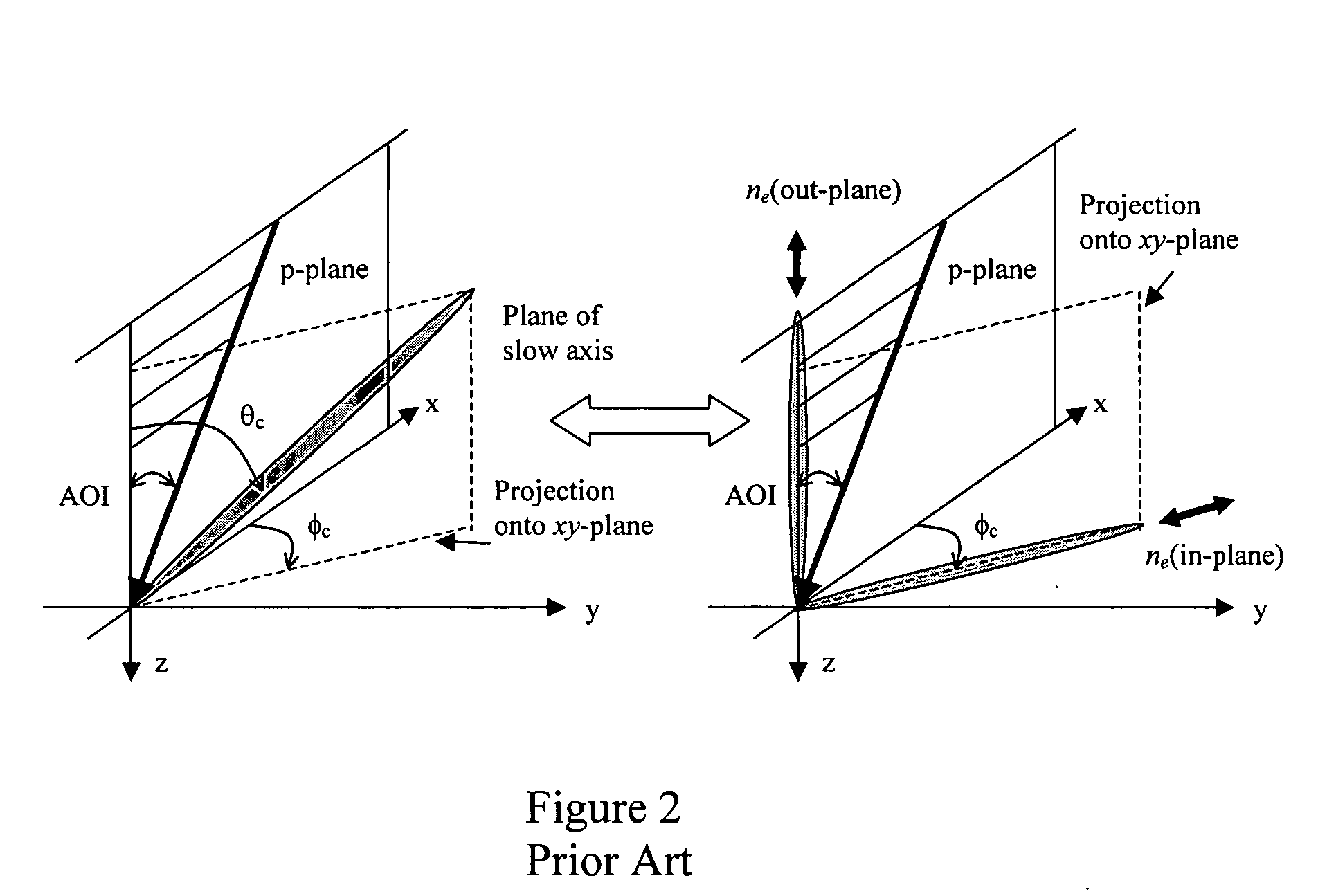
There is quite a mismatch between the relative contribution of the imager IPR and OPR to the overall net retardation under a cone illumination.
Unfortunately, the use of cholesterics with in-plane LC director alignment may present unwanted crossed polarization leakage into an LCOS projection system, due to the high intrinsic material birefringence involved.
Unfortunately, this approach greatly restricts the type of dielectric form birefringence compensator material for use therein, and requires accurate measurement of material constants and coating thicknesses.
Moreover, this method does not take into account the retardance caused by an off-axis reflection from the air / substrate interface.

Method used


Image

  • Trim retarders incorporating negative birefringence
  • Trim retarders incorporating negative birefringence
  • Trim retarders incorporating negative birefringence

Examples


Embodiment Construction

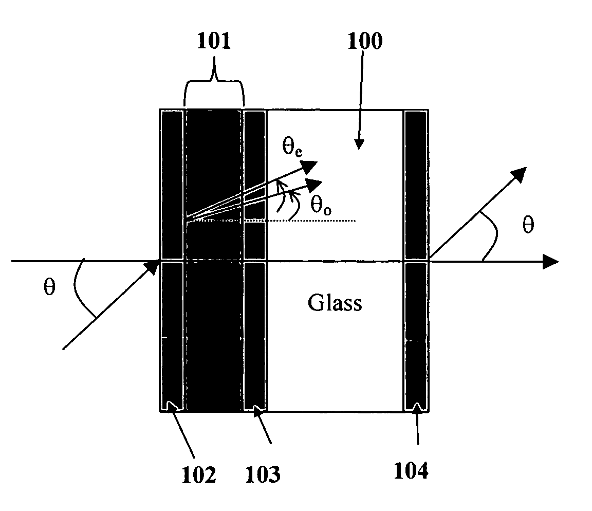
[0082] The present invention relates to the use of dielectric coatings with form birefringence, either as a stand-alone device or integrated with an in-plane retarder, to minimize the leakage intensity of an imager panel within limited cone angles, e.g. up to ±12°, through a pair of crossed polarizers. If the periodic optical isotropic layers are larger than the molecular lengths, but are only a fraction of the operational wavelengths, anisotropy arises from the structure, whereby the c-axis of the negative uniaxial equivalent medium lies in the direction of layer stratification, i.e. parallel to the device normal. The extraordinary and ordinary indices of refraction are given by the Oth order equivalent medium theory (EMT) to be:

no2=(1−f)(n1)2+f(n2)2, and  (3) 1ne2=(1-f)(n1)2+f(n2)2,(4)[0083] where f is the ratio of the n2 index layer thickness to the total thickness of n1 / n2 pair; n1 and n2 are typically low and high index isotropic media. There are also second order EMT expressi...


PUM


Abstract

The present invention relates to trim retarders used to compensate for residual birefringence created by liquid crystal display panels. In particular the present invention relates to a trim retarder with negative out-of-plane birefringence provided by a form birefringent multi-layer dielectric stack for compensating for retardances resulting from liquid crystal on silicon display panels.

Description

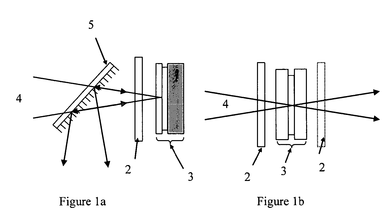
CROSS-REFERENCE TO RELATED APPLICATIONS [0001] The present invention claims priority from U.S. Patent Applications Nos. 60 / 529,315 filed Dec. 11, 2003; 60 / 587,924 filed Jul. 14, 2004; 60 / 589,167 filed Jul. 19, 2004, and 60 / 586,542 filed Jul. 9, 2004, which are incorporated herein by reference.TECHNICAL FIELD [0002] The present invention relates to an optical compensator for polarization based micro-display imagers, e.g. a reflective Liquid-Crystal-on-Silicon (LCOS) or a Transmissive Liquid Crystal Display (xLCD) panel, and in particular to a trim retarder with negative birefringence. BACKGROUND OF THE INVENTION [0003] A trim retarder compensates for residual retardation of the micro-display imager panel in a dark (OFF) state. Unlike typical birefringent waveplates providing ¼λ or ½λ retardation, a typical A-plate trim retarder provides between 1 nm and 50 nm of in-plane retardance. The primary benefit of introducing a trim retarder into a display system is to enhance image contrast,...

Claims


Application Information

Patent Timeline
IPC IPC(8): G02B5/30G02F1/13363
CPCG02B5/3016G02B5/3041G02B5/305G02B5/3083G02F2202/40G02F1/133634G02F1/136277G02F2001/133637G02F2201/30G02F1/133502G02F1/133637
Inventor TAN, KIM LEONGHENDRIX, KAREN DENISEDUELLI, MARKUSHULSE, CHARLES ANDY
Owner VIAVI SOLUTIONS INC
Learn More