Lithographic apparatus and device manufacturing method, and measurement systems

a technology of lithographic apparatus and device, which is applied in the direction of electrical apparatus, instruments, printing, etc., can solve the problems that the current interferometer system for measuring the displacement in the z-direction of the substrate table cannot be used, and the known encoder system may not be suitable for the purpose of measuring the displacement of the substrate table and/or the reticle stage, etc., to achieve the effect of small substrate table, large projection system and less weight of the moveable obj

Inactive Publication Date: 2005-06-16
ASML NETHERLANDS BV
View PDF9 Cites 155 Cited by
  • Summary
  • Abstract
  • Description
  • Claims
  • Application Information

AI Technical Summary

Benefits of technology

[0023] In an embodiment of the invention, the weight of parts of the measuring system that are mounted onto moving parts of the lithographic apparatus are reduced in weight compared to the weight of parts of a conventional measuring system that are mounted onto moving parts of the lithographic apparatus.
[0036] The second gratings may be arranged on opposite sides of the beam source. This way, it is achieved that the encoder system may be less sensitive to changes in the distance between the moveable object and the beam source in the direction of the first beam.
[0038] The grating period of the first grating is chosen such that the angle between the first beam and the second beam and the angle between the first beam and the third beam are relatively small compared to conventional encoders of this type. In an embodiment of the invention, these angles are between 3° and 6°. This way, the displacement of the irradiated location (that is: where the beam touches the grating) on the second gratings is relatively small when the distance between the moveable object and the beams source changes. This way, the length of the second gratings measured in the direction of the parallel lines can be kept relatively small.
[0039] The fourth beam then meets a right roof prism, which directs the fourth beam in the direction opposite to the direction of the second beam, and at an offset distance from the second beam. In the same way, the sixth beam then meets a left roof prism, which directs the sixth beam in the direction opposite to the direction of the third beam, and at an offset distance from the third beam. The left and right roof prism could each (or both) be replaced by a set of reflecting surfaces, which can be, in an embodiment of the invention, at an angle of 90° to each other, thus in fact creating the function of the roof prism by using multiple elements.

Problems solved by technology

However, due to current developments, the layout of the substrate table and the projections change in such a way that it is envisaged that within some time the current interferometer system for measuring the displacements in z-direction of the substrate table can no longer be used.
As the substrate table performs movements significantly larger than 1 mm in its x- and y-directions and the reticle stage performs movements significantly larger than 1 mm in at least its y-direction, known encoder systems may not be suitable for the purpose of measuring z-displacements of the substrate table and / or the reticle stage.

Method used


Image

  • Lithographic apparatus and device manufacturing method, and measurement systems
  • Lithographic apparatus and device manufacturing method, and measurement systems
  • Lithographic apparatus and device manufacturing method, and measurement systems

Examples


Embodiment Construction

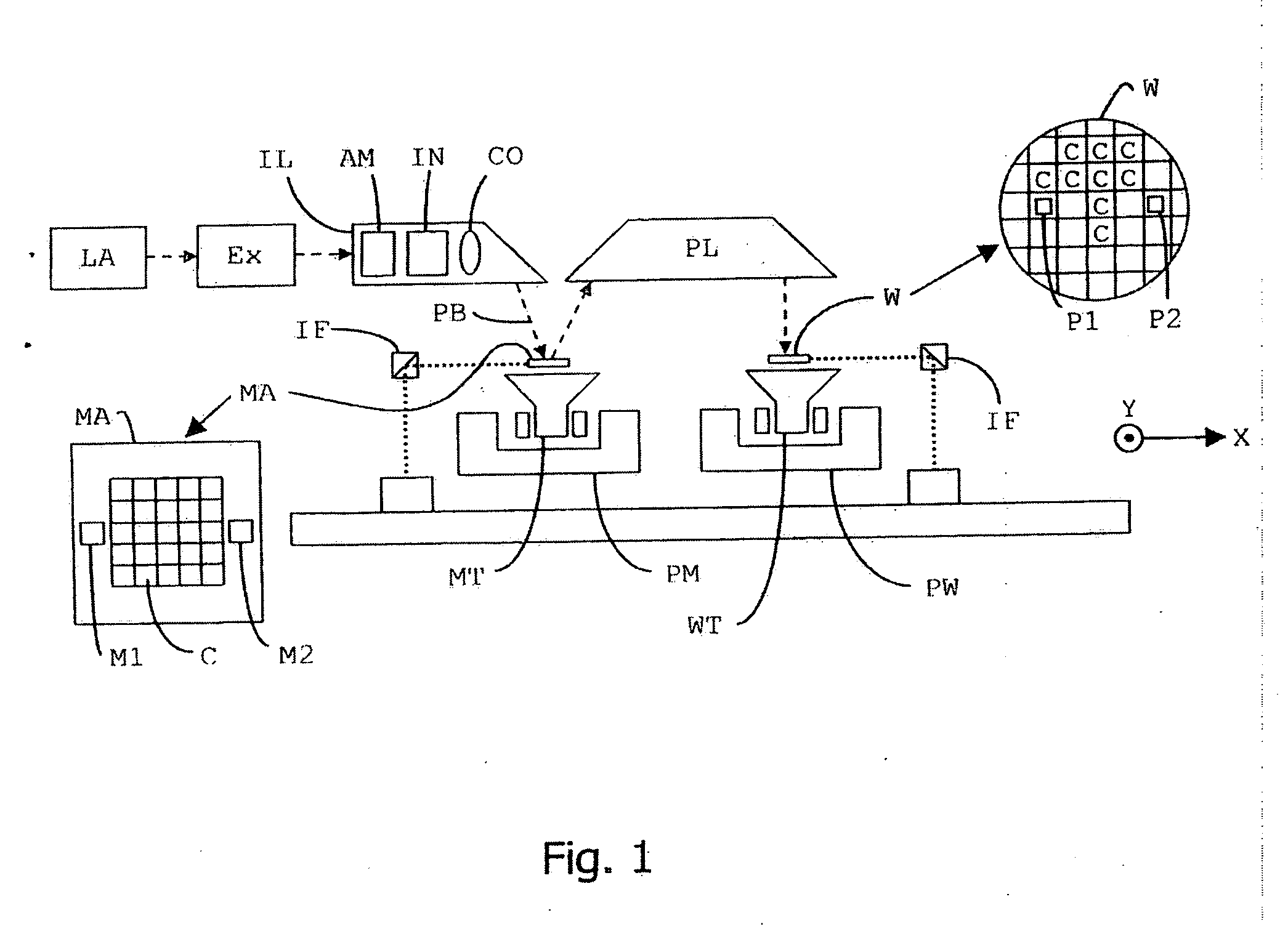
[0083]FIG. 1 schematically depicts a lithographic apparatus according to an embodiment of the invention. The apparatus includes a radiation system Ex, IL, configured to supply a beam PB of radiation (e.g. laser radiation). In this particular case, the radiation system also includes a radiation source LA and a first object table (mask table) MT provided with a mask holder configured to hold a mask MA (e.g. a reticle), and connected to a first positioning device PM configured to accurately position the mask with respect to the projection system (“lens”), item PL. The apparatus also includes a second object table (substrate table) WT provided with a substrate holder configured to hold a substrate W (e.g. a resist-coated silicon wafer), and connected to a second positioning device PW configured to accurately position the substrate with respect to the projection (“lens”), item PL, the projection system (“lens”) PL being configured to image an irradiated portion of the mask MA onto a targ...


PUM

PropertyMeasurementUnit
angleaaaaaaaaaa
angleaaaaaaaaaa
angleaaaaaaaaaa

Abstract

The invention pertains to a lithographic apparatus including a radiation system configured to condition a beam of radiation; a projection system configured to project the beam of radiation onto a target portion of a substrate; a displacement device configured to move the moveable object relative to the projection system in substantially a first direction and a second direction differing from the first direction; and a measuring device configured to measure a displacement of the moveable object in a third direction, which is substantially perpendicular to the first direction and to the second direction, wherein the measuring device may include an encoder system.

Description

1. PRIORITY INFORMATION [0001] This application claims priority from European Patent Application No.03078338.5, filed Oct. 22, 2003, the content of which is herein incorporated by reference in its entirety. BACKGROUND [0002] 2. Field of the Invention [0003] The present invention relates to lithographic apparatus and methods [0004] 3. Description of Related Art [0005] The term “patterning device” as here employed should be broadly interpreted as referring to a device that can be used to endow an incoming radiation beam with a patterned cross-section, corresponding to a pattern that is to be created in a target portion of the substrate; the term “light valve” can also be used in this context. Generally, the pattern will correspond to a particular functional layer in a device being created in the target portion, such as an integrated circuit or other device (see below). Examples of such patterning devices include: [0006] A mask. The concept of a mask is well known in lithography, and i...

Claims


Application Information

Patent Timeline
Patent Type & Authority Applications(United States)
IPC IPC(8): G01B11/00G03F7/20H01L21/027
CPCG03F7/70775
Inventor BEEMS, MARCEL HENDRIKUS MARIAVAN DER PASCH, ENGELBERTUS ANTONIUS FRANSISCUS
Owner ASML NETHERLANDS BV
Why Eureka
Try Eureka