Light measuring apparatus and a method for correcting non-linearity of a light measuring apparatus

a light measuring apparatus and nonlinearity technology, applied in the direction of optical radiation measurement, instruments, spectrophotometry/monochromators, etc., can solve the problem of not having linearity normally required for measuring apparatuses, requiring considerable labor and time for adjustment, and requiring large facilities. , to achieve the effect of high precision and efficient correction of nonlinearity

Active Publication Date: 2005-06-16
KONICA MINOLTA SENSING INC
View PDF3 Cites 20 Cited by
  • Summary
  • Abstract
  • Description
  • Claims
  • Application Information

AI Technical Summary

Benefits of technology

[0021] An object of the present invention is to provide a light measuring apparatus and non-linearity correcting method which can h

Problems solved by technology

However, if the resistance value is switched in a stepwise manner as described above, input/output relationships at the respective gains become discontinuous and cannot be linear as shown in FIG. 18 because of the deviation of the resistance values from nominal values.
Such CCD have an S-shaped input/output relationship due to its characteristics such as the saturation of a photoelectrically converting characteristic as shown in FIG. 19 and, hence, has a problem of not having linearity normally required for measuring apparatuses.
Accordingly, any of the known techniques has problems of necessitating a large facility and requiring considerable

Method used


Image

  • Light measuring apparatus and a method for correcting non-linearity of a light measuring apparatus
  • Light measuring apparatus and a method for correcting non-linearity of a light measuring apparatus
  • Light measuring apparatus and a method for correcting non-linearity of a light measuring apparatus

Examples


first embodiment

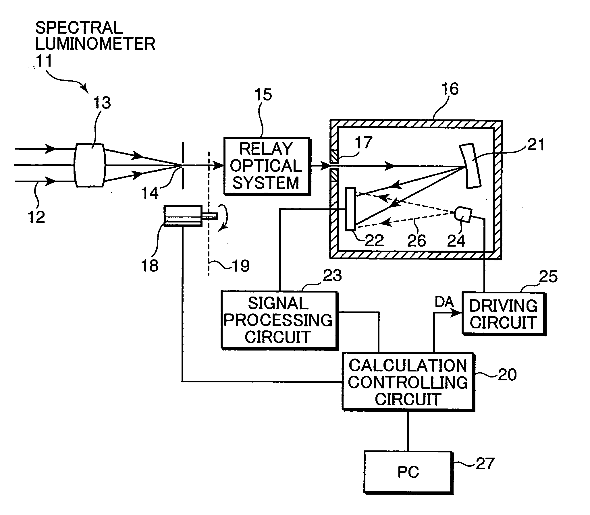
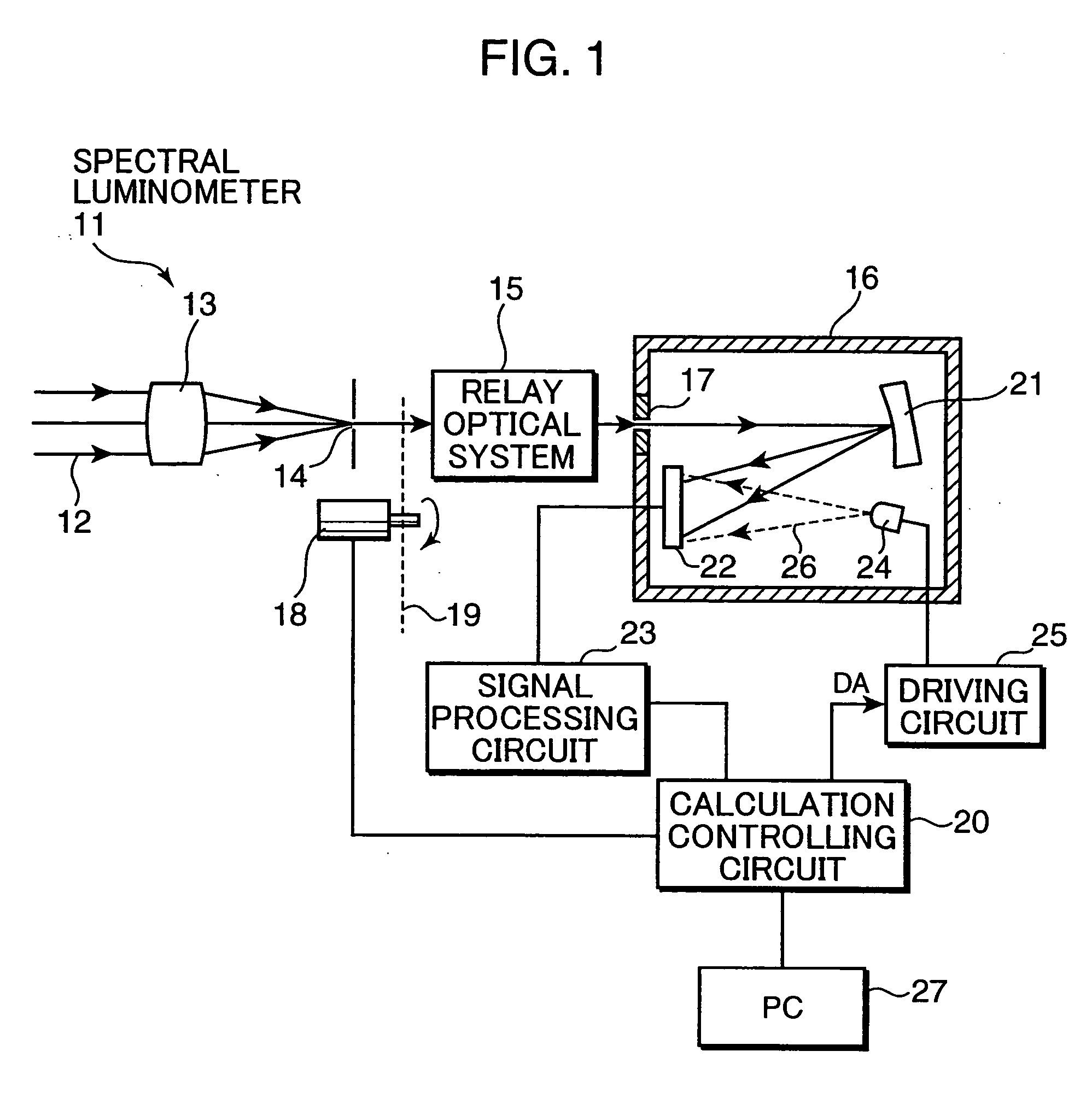
[0043]FIG. 1 is a block diagram showing a construction of a spectral luminometer 11 according to a first embodiment of the present invention. This spectral luminometer 11 has a function of correcting the discontinuity of an input / output characteristic resulting from the switching of a gain as shown in FIG. 18. Light being measured or measurement light 12 is converged toward a measurement area restricting opening 14 by a light receiving optical system 13 and is caused to form an image of the measurement area restricting opening 14 and converged toward an incidence opening 17 of a polychrometer 16 by a relay optical system 15. A shutter 19 driven by a driving device 18 is provided behind the measurement area restricting opening 14. The driving device 18 is controlled by a calculation controlling circuit 20. The shutter 19 is closed while no measurement is conducted and while a correction to be described later is made, whereas it is opened during a measurement to control the incidence ...

second embodiment

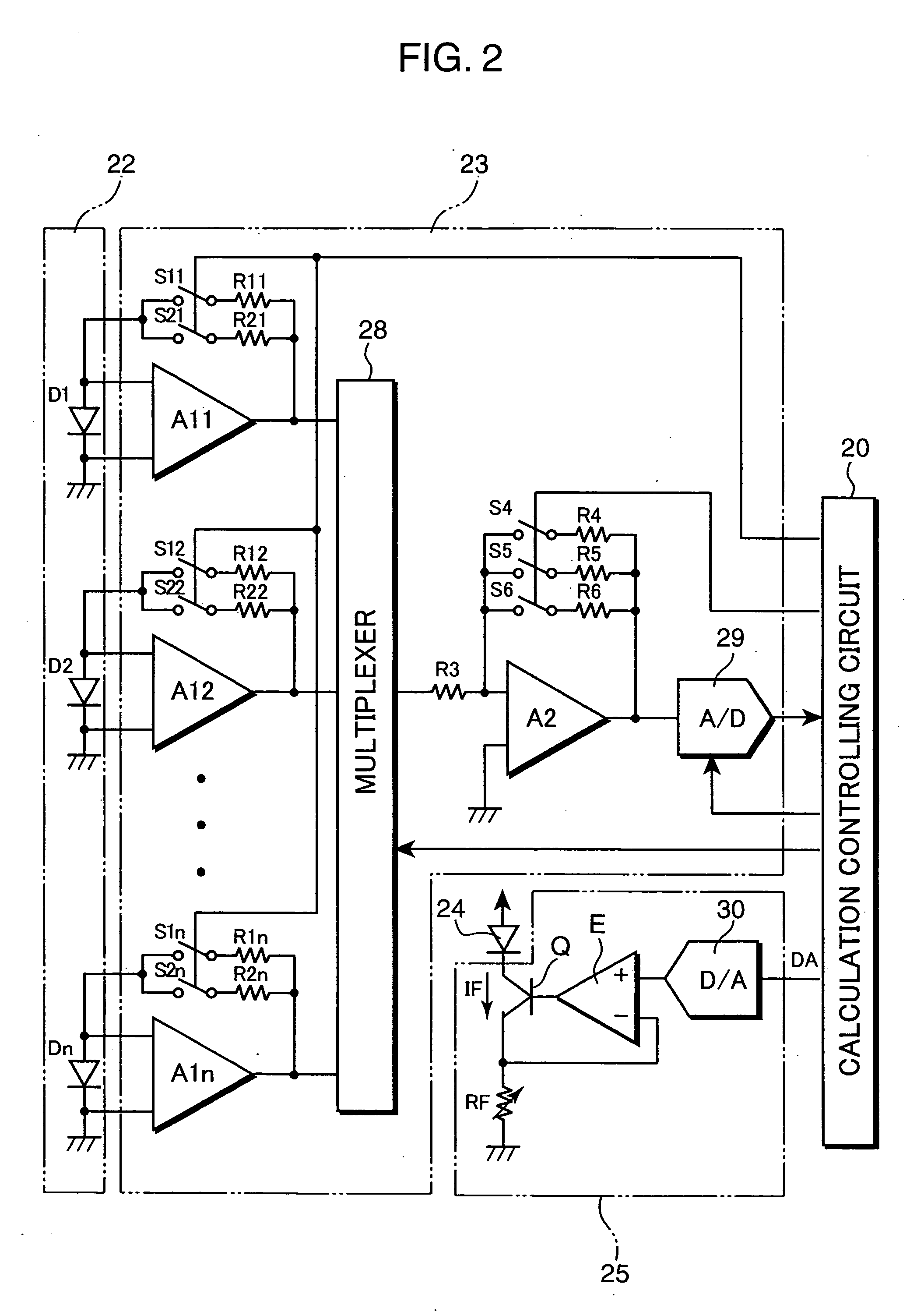
[0082]FIG. 5 is a block diagram showing a construction of a spectral luminometer 31 according to a second embodiment of the invention. This spectral luminometer 31 is similar to the aforementioned spectral luminometer shown in FIG. 1, and no description is given on corresponding parts and elements thereof by identifying them by the same reference numerals. What should be noted is that the light receiving sensor array 22 is comprised of silicon photodiodes, the amplifiers Al for the current-to-voltage conversion are provided for the respective photodiodes D1 to Dn as shown in FIG. 2, and the gains (sensitivities) are switched by switching the feedback resistors R1, R2; R4, R5, R6 of the amplifiers A1, A2 in the aforementioned spectral luminometer 11, whereas a light receiving sensor array 32 is a CCD and the gains (sensitivities) are also switched according to integration times of electric charges stored into the CCD in the spectral luminometer 31.

[0083] Accordingly, this spectral l...

third embodiment

[0112]FIG. 9 is a block diagram showing a construction of a spectral luminometer 71 according to a third embodiment of the present invention. This spectral luminometer 71 is similar to the aforementioned spectral luminometer 31, and no description is given on the corresponding parts and elements thereof by identifying them by the same reference numerals. This spectral luminometer 71 is further provided with an integrating sphere 72 having a paint of high reflectivity and high dispersing property applied to the inner surface thereof, and a light source 73 provided therein.

[0113] When a driving circuit 74 causes the light source 73 to emit light in accordance with an emission control signal from the calculation controlling circuit 20b, this output light is diffused and reflected by the inner surface of the integrating sphere 72 to illuminate a sample 76 placed at a sample opening 75. A component 77 of the light reflected by the sample in an observing direction is received by a light ...


PUM


Abstract

A correction LED is provided to illuminate a light receiving sensor array, and a calculation controlling circuit calculates correction values at the respective illuminance levels based on sensor output levels expected at the respective illuminance levels and actual sensor output levels while successively turning the correction LED on at a plurality of illuminance levels whose illuminance ratios are at least known, and corrects a sensor output level by the corresponding correction value to obtain a measurement output at the time of an actual measurement. The discontinuity of an input/output characteristic resulting from the switching of gains of an amplifier for amplifying a photocurrent and the non-linearity caused by the saturation of the photoelectrically converting characteristic of the optical sensor and the exponential characteristics of the optical sensor and the amplifier can be corrected without employing a large-scale construction such as a bench. The non-linearity can be highly precisely and efficiently corrected in a measuring apparatus realized as a spectral luminometer or a spectral calorimeter without requiring a special facility.

Description

[0001] This application is based on Japanese patent application No. 2003-392456 filed on Nov. 21, 2003, the contents of which are hereby incorporated by references. BACKGROUND OF THE INVENTION [0002] The present invention relates to a light measuring apparatus adapted to measure the intensity of light being measured and suitably usable as a spectral luminometer or a spectral calorimeter and a method for correcting the non-linearity of such a light measuring apparatus. [0003] A polychrometer for simultaneously measuring spectral intensities of all the wavelengths in a measurement wavelength range is widely used as the one of a spectral luminometer (spectral intensity measuring apparatus) for measuring a spectral intensity distribution of light being measured or as the one of a spectral calorimeter (spectral reflection characteristic measuring apparatus) for measuring a spectral reflection characteristic of a sample due to its high measurement efficiency, its capability of measuring a...

Claims


Application Information

Patent Timeline
IPC IPC(8): G01J3/02G01J1/04G01J1/08G01J1/16G01J1/42G01J1/44G01J3/18G01J3/28G01N21/27G01N21/31
CPCG01J1/08G01J1/1626G01J1/4228G01J2001/0481G01N2201/12723G01N21/274G01N21/31G01N2201/0623G01N2201/127G01J2003/2866
Inventor IMURA, KENJI
Owner KONICA MINOLTA SENSING INC
Why Eureka
Try Eureka