Wide-band spectrometer with objective comprising an aspherical corrector mirror

a wide-band spectrometer and corrector mirror technology, applied in the field of spectrometers, can solve the problems of high undesirable aberration, so-called spatial co-registration error, general undesirable effects, etc., and achieve the effect of reducing or eliminating chromatic aberration

Inactive Publication Date: 2005-06-16
GALILEO AVIONICA
View PDF0 Cites 27 Cited by
  • Summary
  • Abstract
  • Description
  • Claims
  • Application Information

AI Technical Summary

Benefits of technology

[0040] An object of the present invention is to provide a spectrometer that enables reduction of the errors referred to above and reduction or elimination of chromatic aberration.
[0042] The aspherical mirror may form part of the collimator or else form part of the focusing system. Preferably, also a second aspherical corrector element is provided. This may consist of a dioptric Schmidt plate, i.e., one that works in transmission, with the beam to be corrected that traverses the plate itself instead of being reflected from it. However, to obtain qualitatively superior results, according to a further improvement of the present invention also the second aspherical corrector element is a reflecting element, i.e., an aspherical mirror. This makes it possible to prevent any introduction of a chromatic aberration that cannot be eliminated in dioptric Schmidt plates, i.e., that work in transmission.
[0043] To eliminate also the curvature of field without any constraints as to a particular choice of the focal lengths and as to a particular orientation of the optical devices that make up the system, according to a particularly advantageous embodiment the use is envisaged of a divergent spherical mirror (preferably associated to the collimator), which eliminates the curvature of field and of slit. This mirror is preferably set directly downstream of the beam-entry slit, between the latter and the converging mirror of the collimator.

Problems solved by technology

Using refractive or prismatic dispersors in an imaging spectrometer or diffraction gratings provided on curved surfaces, there may arise a phenomenon, which is generally undesirable, referred to as “curvature of the image of the slit”, or “curvature of slit”, or “smile”.
In addition to the above error, in this kind of apparatus there may also occur a so-called spatial co-registration error.
This type of error derives from a chromatic variation of the magnification as a function of the field of view.
Since in an imaging spectrometer the sensitive elements of the detector generally lie in a plane, this aberration is highly undesirable and must be contained within the depth of focus or of field of the optical system, which is linearly dependent upon the wavelength and quadratically dependent upon the speed or f number.

Method used


Image

  • Wide-band spectrometer with objective comprising an aspherical corrector mirror
  • Wide-band spectrometer with objective comprising an aspherical corrector mirror
  • Wide-band spectrometer with objective comprising an aspherical corrector mirror

Examples


Embodiment Construction

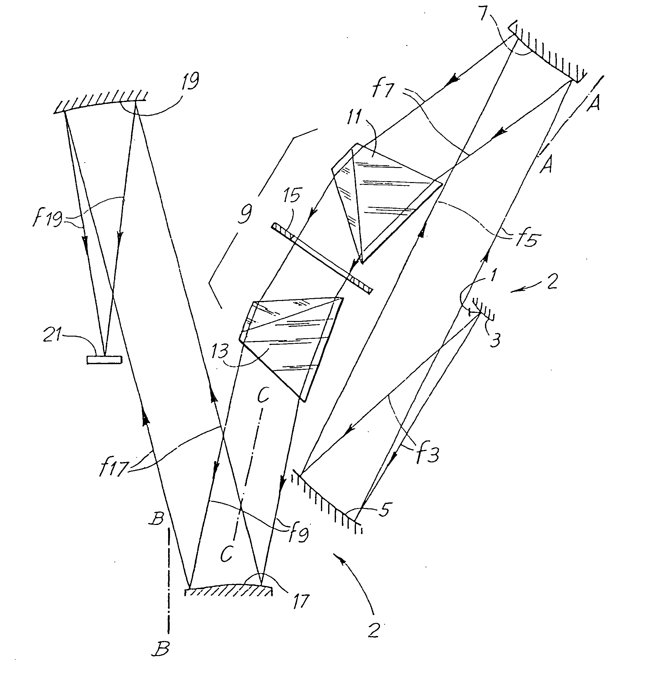
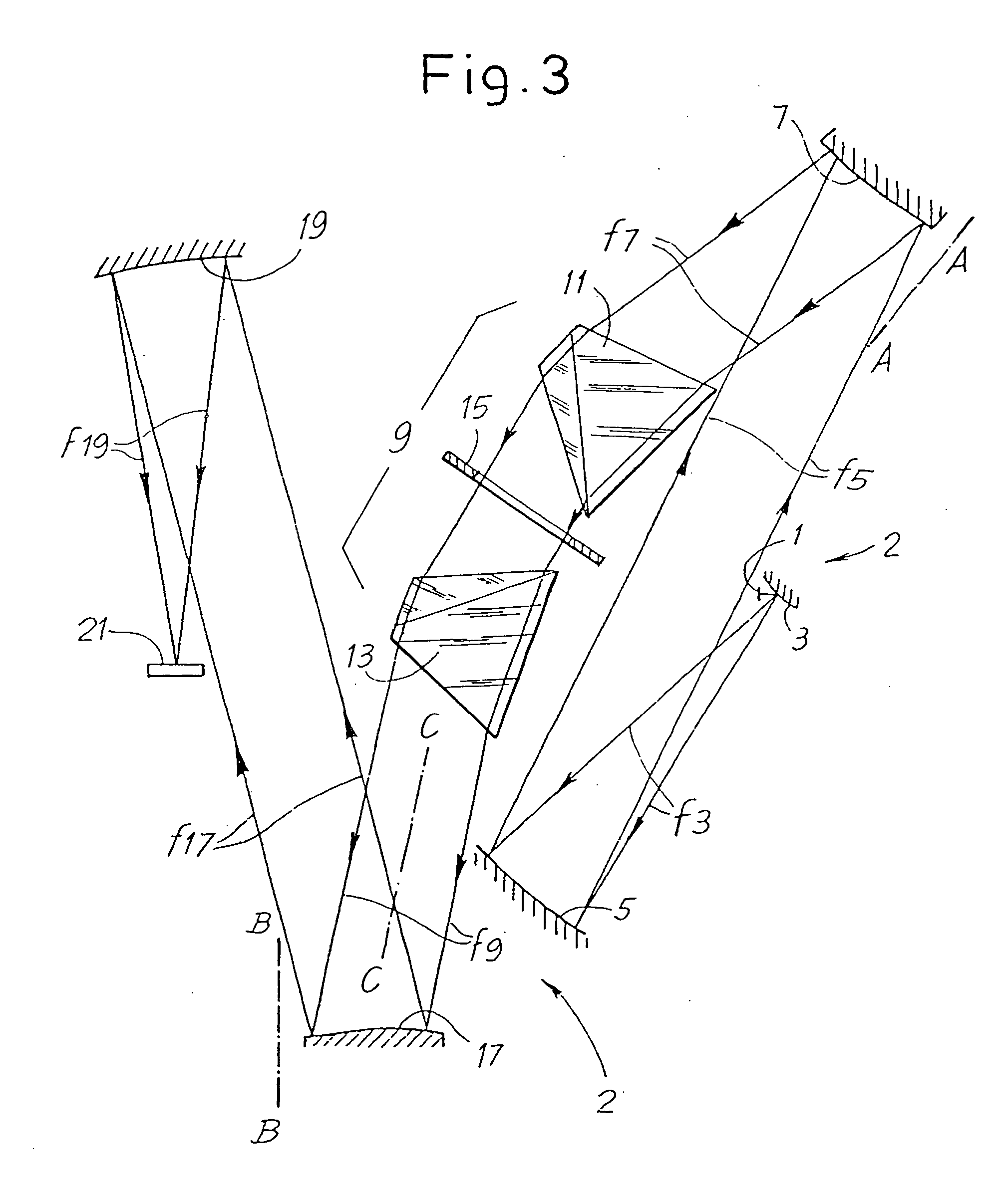
[0079]FIG. 3 shows a first possible embodiment of the spectrometer according to the present invention, indicated as a whole by 2. Along the optical path of the incoming beams or incoming entry optics, the spectrometer has a beam-entry slit 1 which extends orthogonally to the plane of the figure. Through this slit there penetrate beams coming from a beam-entry optical device, which does not form part of the spectrometer and is not shown. Said optical device has characteristics which can vary according to the specific application for which the spectrometer is designed. The incoming beam or the incoming entry optics beam passing through the slit 1 encounters a first divergent spherical mirror 3, which has the function of correcting the curvature of field and the curvature of slit (smile). The beam reflected by the mirror 3 (beam F3) then encounters a convergent spherical mirror 5, which constitutes the mirror of a Schmidt objective which forms the collimator of the spectrometer. The co...


PUM


Abstract

The spectrometer comprises at least a first optical path for a beam of electromagnetic radiation, along which the following are set: a beam-entry slit (1) for an incoming beam; a collimator (5) comprising a convergent spherical mirror for collimation of the incoming beam; a first dispersor (9) for dispersion of the beam into its chromatic components; a first focusing system (19); and a first detector (21) which receives the beam dispersed and focused by said first focusing system. Set along the first optical path there is set at least one first aspherical corrector element (7; 17) comprising an aspherical mirror for correction of spherical aberration.

Description

CROSS REFERENCE TO RELATED APPLICATION [0001] This is a continuation of U.S. patent application with Ser. No. 10 / 153,514. The entire contents of each application is hereby incorporated by reference in its entirety.FIELD OF THE INVENTION [0002] The present invention relates to spectrometers, and in particular but not exclusively to imaging spectrometers. BACKGROUND OF THE INVENTION [0003] A spectrometer is an optical system that conjugates an object in a superposition of chromatic images on the image plane in which a detector is located. [0004] The images of each wavelength are translated in a direction, referred to as spectral direction, by an amount that depends upon the wavelength and follows a law of chromatic dispersion. [0005] The object in the spectrometer is frequently an image coming from another optical system. [0006] The object observed by the spectrometer is generally delimited by a rectangular diaphragm of field, referred to as slit. [0007] The spatial direction and the ...

Claims


Application Information

Patent Timeline
Patent Type & Authority Applications(United States)
IPC IPC(8): G01J3/02G01J3/14G01J3/28G01J3/36
CPCG01J3/02G01J3/0208G01J3/36G01J3/2823G01J3/14
Inventor CARUSO, ALBERTOROMOLI, ANDREATACCOLA, MATTEO
Owner GALILEO AVIONICA
Why Eureka
Try Eureka