Scanner system

a scanner and system technology, applied in the field of scanner systems, can solve the problems of uniform angle command pattern and several micrometer allocation error of the scanner system, and achieve the effect of quick positioning and improved machining speed

Active Publication Date: 2005-06-16
HITACHI SEIKO LTD
View PDF12 Cites 25 Cited by
  • Summary
  • Abstract
  • Description
  • Claims
  • Application Information

AI Technical Summary

Benefits of technology

[0016] The mirror can be positioned quickly, and the machining speed can be improved. In addition, in spite of the variation of the angle command, the fluctuation in settling response of the galvanometer mirror can be suppressed so that the response can always be made quick.

Problems solved by technology

In the whole error, the allocatable error to the scanner system is about several micrometers.
Further, the angle command pattern is not uniform, but is varied in mirror travel angle or time interval.

Method used


Image

  • Scanner system
  • Scanner system
  • Scanner system

Examples


Embodiment Construction

[0021] The present invention will be described below with reference to an embodiment shown in the drawings.

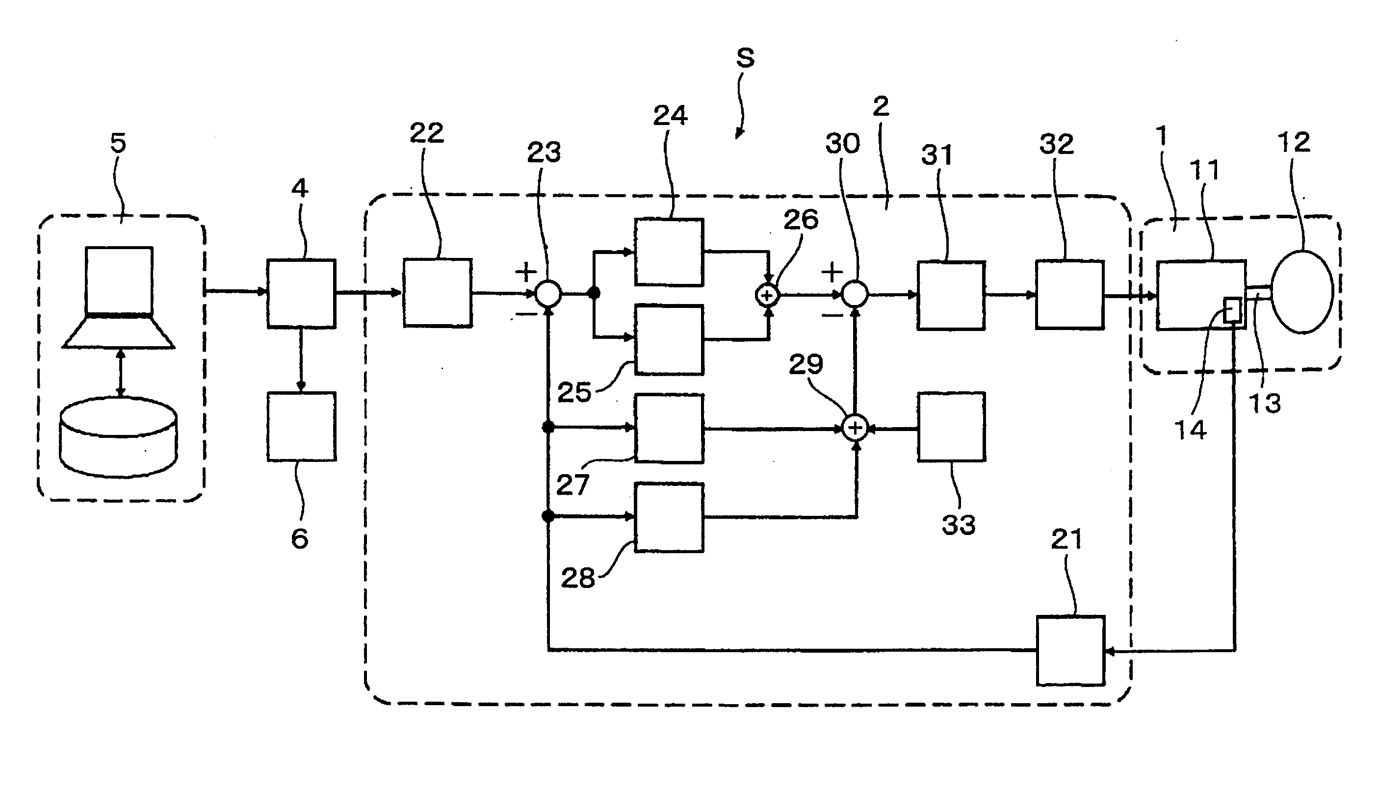
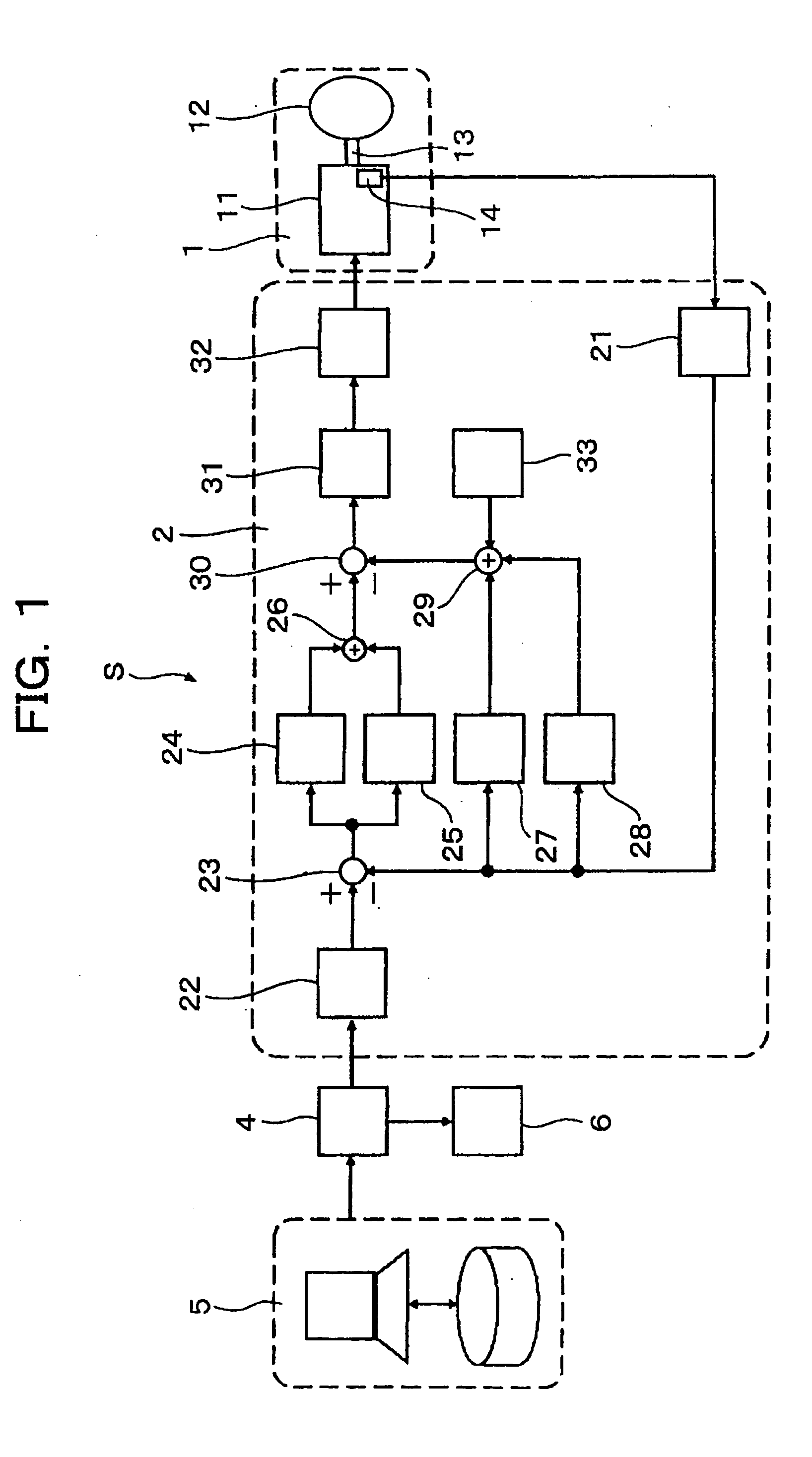
[0022]FIG. 1 is a block diagram of a laser machining apparatus having a scanner system according to the present invention.

[0023] A control unit 5 of the laser machining apparatus outputs coordinate data of machining positions to an upper control unit 4 based on a machining program inputted to the control unit 5. The upper control unit 4 converts the inputted coordinate data into angle commanded values for controlling a mirror 12, and transmits the angle commanded values to a servo control unit 2. In this event, the upper control unit 4 controls the timing of transmitting the angle commanded values so as to synchronize them with pulses output from the laser oscillator 6.

[0024] A scanner system S in this embodiment is constituted by a trajectory generator 22, the servo control unit 2 and a scanner 1.

[0025] The trajectory generator 22 smoothly interpolates the step-like angle ...


PUM

PropertyMeasurementUnit
timeaaaaaaaaaa
rotation angleaaaaaaaaaa
stabilityaaaaaaaaaa

Abstract

A scanner system includes a servo control unit. A rotation angle of a rotating shaft supporting a mirror is detected, and an error of the detected value with respect to a commanded value is integrated by an integral compensator so that the detected value is able to track the commanded value. A tracking error proportional compensator is disposed in parallel with the integral compensator so as to add a correction value proportional to the error to the integrated value of the error. A plurality of gains are prepared for each of the integral compensator, the tracking error proportional compensator, a detected value proportional compensator and a detected value differential compensator of the servo control unit. Each gain is changed in accordance with a travel angle of the commanded value. Thus, the mirror can be positioned quickly so that the machining speed can be improved.

Description

FIELD OF THE INVENTION [0001] The present invention relates to a scanner system for detecting a rotation angle of a rotating shaft supporting a galvanometer mirror, and controlling the rotating shaft so as to position the galvanometer mirror in a desired angular position. DESCRIPTION OF THE BACKGROUND ART [0002] A scanner system is a device in which a rotating shaft supporting a galvanometer mirror (hereinafter referred to as “mirror”) is rotated by a motor so that the reflective surface of the mirror is positioned at a desired angle. Thus, for example, a piece to be machined is irradiated at a predetermined position with a laser beam output from a laser oscillator. The scanner system is used in a laser perforating machine (hereinafter referred to as “laser machining apparatus”) for manufacturing printed circuit boards. [0003] In the laser machining apparatus, the speed (responsiveness) to position the mirror and the error thereof with respect to a commanded value have enormous infl...

Claims


Application Information

Patent Timeline
Patent Type & Authority Applications(United States)
IPC IPC(8): G02B26/10H05K3/00
CPCB23K26/08H05K3/0026G02B26/105B23K26/0807B23K26/082B23K26/0821G02B7/1821G02B26/127
Inventor TOYAMA, SOUICHIOTSUKI, HARUAKISAKAMOTO, ATSUSHISEKI, KENTAOKUBO, YAICHI
Owner HITACHI SEIKO LTD
Why Eureka
Try Eureka