Control device of switching device and control device of driving circuit of motor

a technology of control device and driving circuit, which is applied in the direction of dc-ac conversion without reversal, emergency protective arrangements for limiting excess voltage/current, and pulse technique, etc. it can solve the problems of increasing surge voltage, increasing power loss, and driving device may interfere with the car's drive, so as to prevent an increase in surge voltage and increase in power loss

Active Publication Date: 2005-06-16
MITSUBISHI ELECTRIC CORP
View PDF2 Cites 53 Cited by
  • Summary
  • Abstract
  • Description
  • Claims
  • Application Information

AI Technical Summary

Benefits of technology

[0007] It is an object of the present invention to provide a control device of switching devices that prevents an increase in surge voltage and an increase in power loss even when a malfunctio...

Problems solved by technology

Suppression of a surge voltage at switching time and power loss reduction present important problems in those switching devices.
The addition of a snubber circuit to that configuration may result in an increase in the surge voltage or an increase in power loss in ca...

Method used


Image

  • Control device of switching device and control device of driving circuit of motor
  • Control device of switching device and control device of driving circuit of motor
  • Control device of switching device and control device of driving circuit of motor

Examples


Embodiment Construction

[0024]

[0025] A preferred embodiment of a control device of switching devices according to the present invention will be described with reference to FIGS. 1 to 7.

[0026]

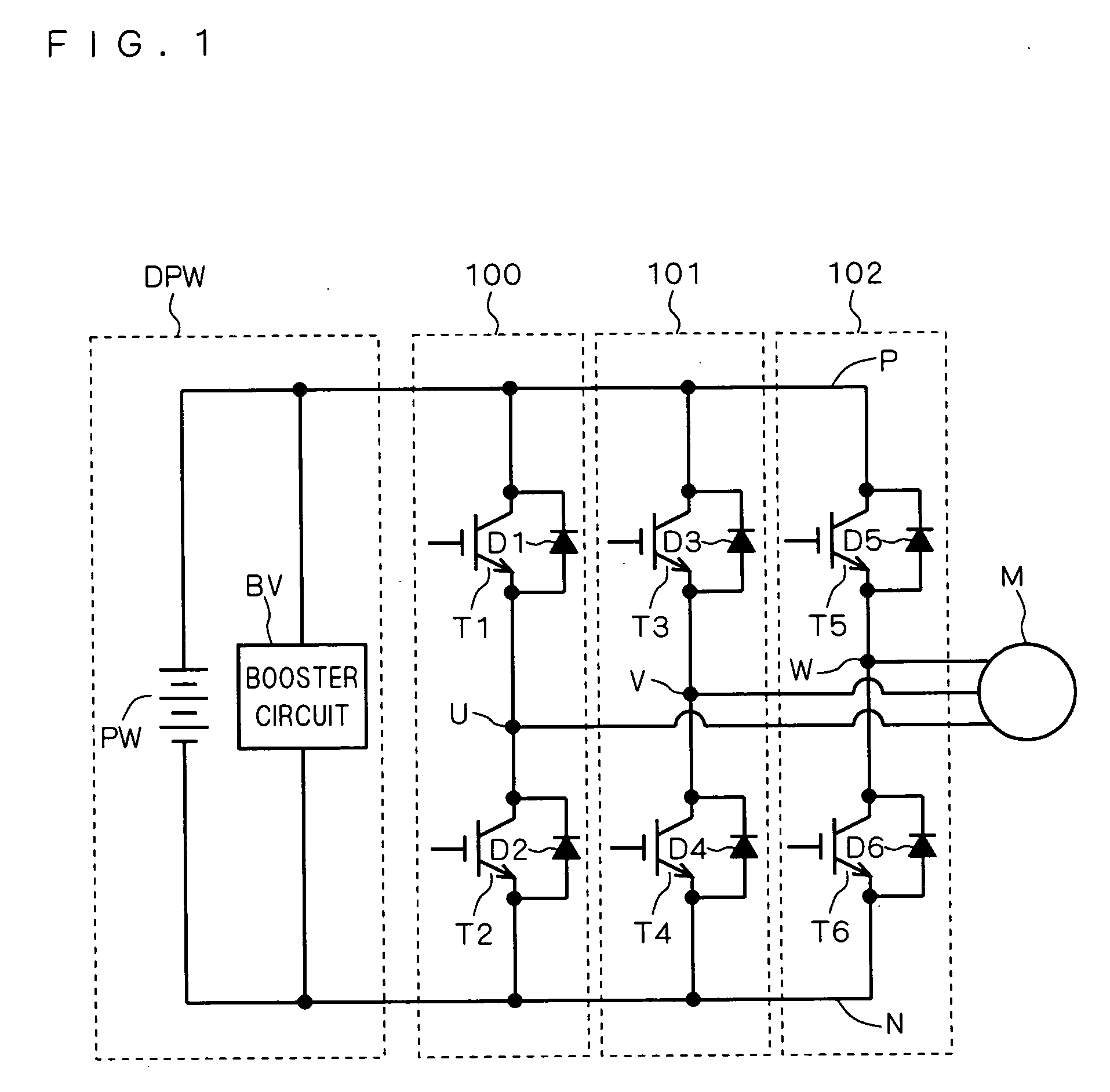
[0027]FIG. 1 illustrates a configuration of a driving circuit of a three-phase motor including power convertors each including the control device of the switching devices according to the invention. As shown in FIG. 1, a main power supply DPW serving as a power supply of the three-phase motor M is disposed between P-N lines, and inverters 100, 101, 102 are independently connected as the power convertors to each phase of the motor M.

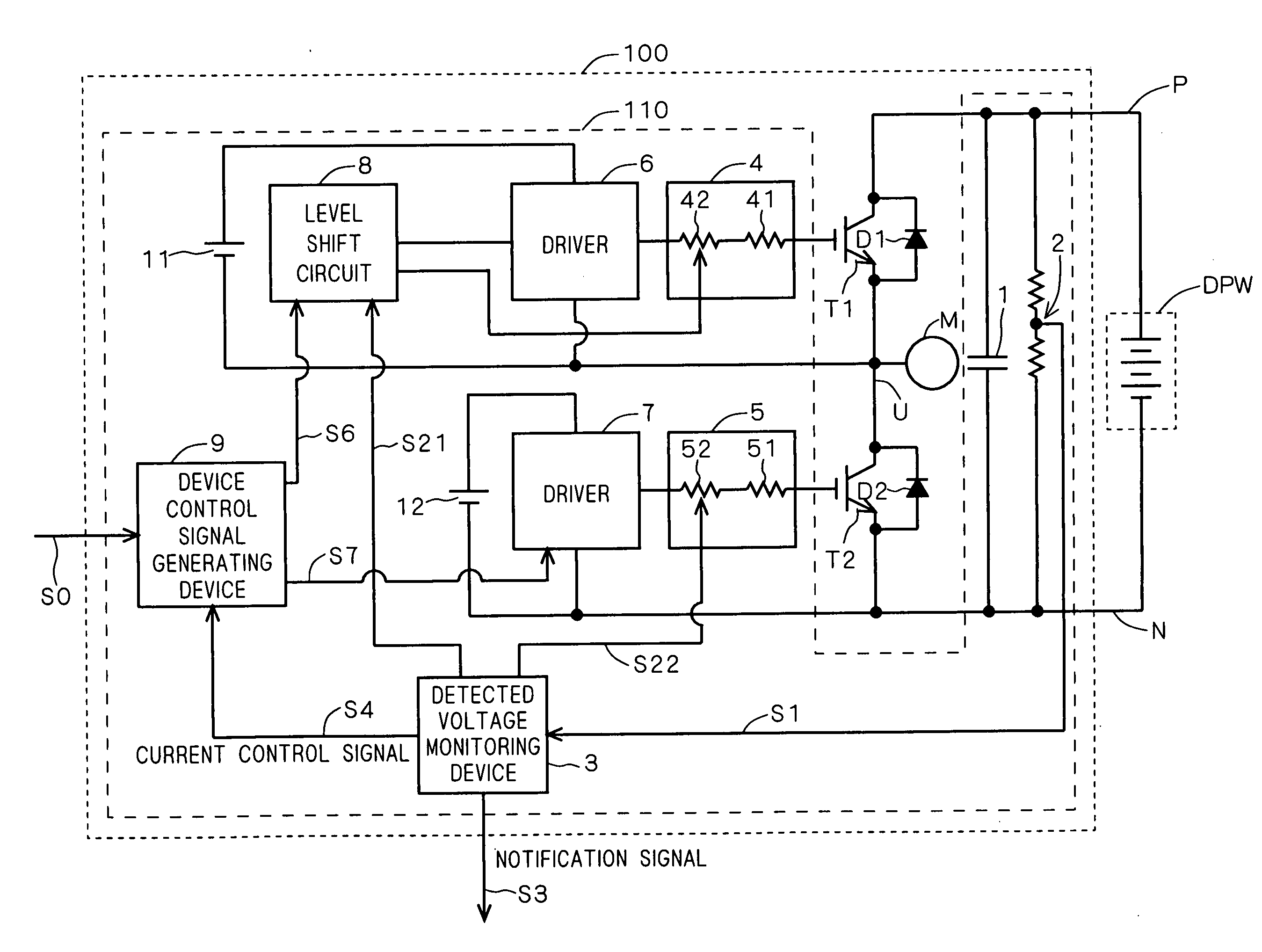
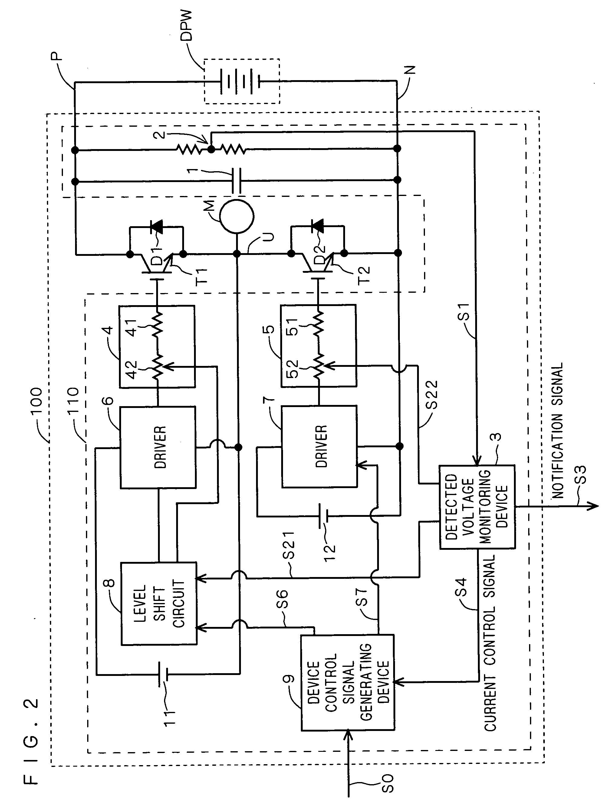
[0028] The inverters 100, 101, 102 include pairs of transistors T1 and T2, T3 and T4, T5 and T6, respectively, the transistors being power devices such as an IGBT totem-pole-connected between the P-N lines. The totem-pole-connected transistors T1 and T2, T3 and T4, T5 and T6 each form a half bridge, and an input terminal of each phase of the motor M is connected to output terminals U, V, W...


PUM


Abstract

A control device includes a capacitor disposed between P-N lines and constituting a snubber circuit, and a voltage detection resistor for detecting a voltage between the P-N lines by dividing resistances to detect surge voltages of transistors, in which gate control signals are provided from drivers to the transistors through gate resistance variable devices, respectively. The gate resistance variable devices include variable resistors, respectively, and the resistance values of the variable resistors are controlled based on variable resistor control signals provided from a detected voltage monitoring device, respectively.

Description

BACKGROUND OF THE INVENTION [0001] 1. Field of the Invention [0002] The present invention relates to a control device of switching devices, and more particularly to a control device of switching devices including a snubber circuit for suppressing a surge voltage. [0003] 2. Description of the Background Art [0004] Power convertors such as inverters use a power MOSFET, an IGBT (Insulated Gate Bipolar Transistor) or the like as switching devices. Suppression of a surge voltage at switching time and power loss reduction present important problems in those switching devices. [0005] For example, Japanese Patent Application Laid-Open No. 2001-217697 (FIG. 1) discloses a driving device of a semiconductor device which, by connecting two resistance variable means to a gate of a switching device a surge voltage of which should be suppressed, dividing a control voltage and applying it to the switching device as a gate voltage, suppresses a temporal variation in the gate voltage to suppress the ...

Claims


Application Information

Patent Timeline
IPC IPC(8): H02M7/48H03K17/082H03K17/16H03K17/56
CPCH03K17/0828H02M7/538
Inventor MIYAMOTO, NOBORU
Owner MITSUBISHI ELECTRIC CORP
Why Eureka
Try Eureka