Composite cold plate assembly

a technology of composite cold plate and assembly, which is applied in the direction of cooling/ventilation/heating modification, semiconductor device details, semiconductor/solid-state device details, etc., can solve the problems of increasing device temperature, power dissipation, and therefore heat production, and achieves sufficient assembly flexibility, good thermal contact, and reduced mechanical conduit connections

Inactive Publication Date: 2005-06-16
IBM CORP
View PDF15 Cites 129 Cited by
  • Summary
  • Abstract
  • Description
  • Claims
  • Application Information

AI Technical Summary

Benefits of technology

[0012] It is a further object of the present invention to provide a multi-cold plate fluid distribution assembly that is simultaneously capable of providing a reliability benefit by reducing mechanical conduit connections, while also providing sufficient assembly flexibility to maintain good thermal contact between assembly cold plates and their associated electronic devices in the presence of normal manufacturing and assembly process tolerances.

Problems solved by technology

This heat should be removed from the devices in order to maintain device junction temperatures within desirable limits: failure to remove the heat thus produced results in increased device temperatures, potentially leading to thermal runaway conditions.
First, power dissipation, and therefore heat production, increases as the device operating frequencies increase.
Finally, as more and more devices are packed onto a single chip, power density (Watts / cm2) increases, resulting in the need to remove more power from a given size chip or module.
These trends have combined to create applications where it is no longer desirable to remove the heat from modern devices solely by traditional air cooling methods, such as by using traditional air cooled heat sinks.
A multi-cold plate fluid distribution assembly constructed using known methods and materials, however, may not provide sufficient flexibility to maintain adequate thermal contact with all associated electronic devices.
Constructing a multi-cold plate fluid distribution assembly using known materials and methods, such as using copper or other metal tubing soldered or brazed to several metal cold plates, results in an assembly that may lack sufficient flexibility to maintain good thermal contact in the presence of normal manufacturing and assembly process variations.
Alternatively, known materials and methods may be used to create a multi-cold plate fluid distribution assembly having sufficient flexibility but which lacks the reliability improvements associated with a reduced number of mechanical conduit connections.
As previously noted, increasing the number of mechanical conduit connections increases the potential points of failure in the cooling distribution assembly.

Method used


Image

  • Composite cold plate assembly
  • Composite cold plate assembly
  • Composite cold plate assembly

Examples


Embodiment Construction

[0025] In accordance with preferred embodiments of the present invention, a multi-cold plate fluid distribution assembly utilizing a composite cold plate structure is disclosed herein.

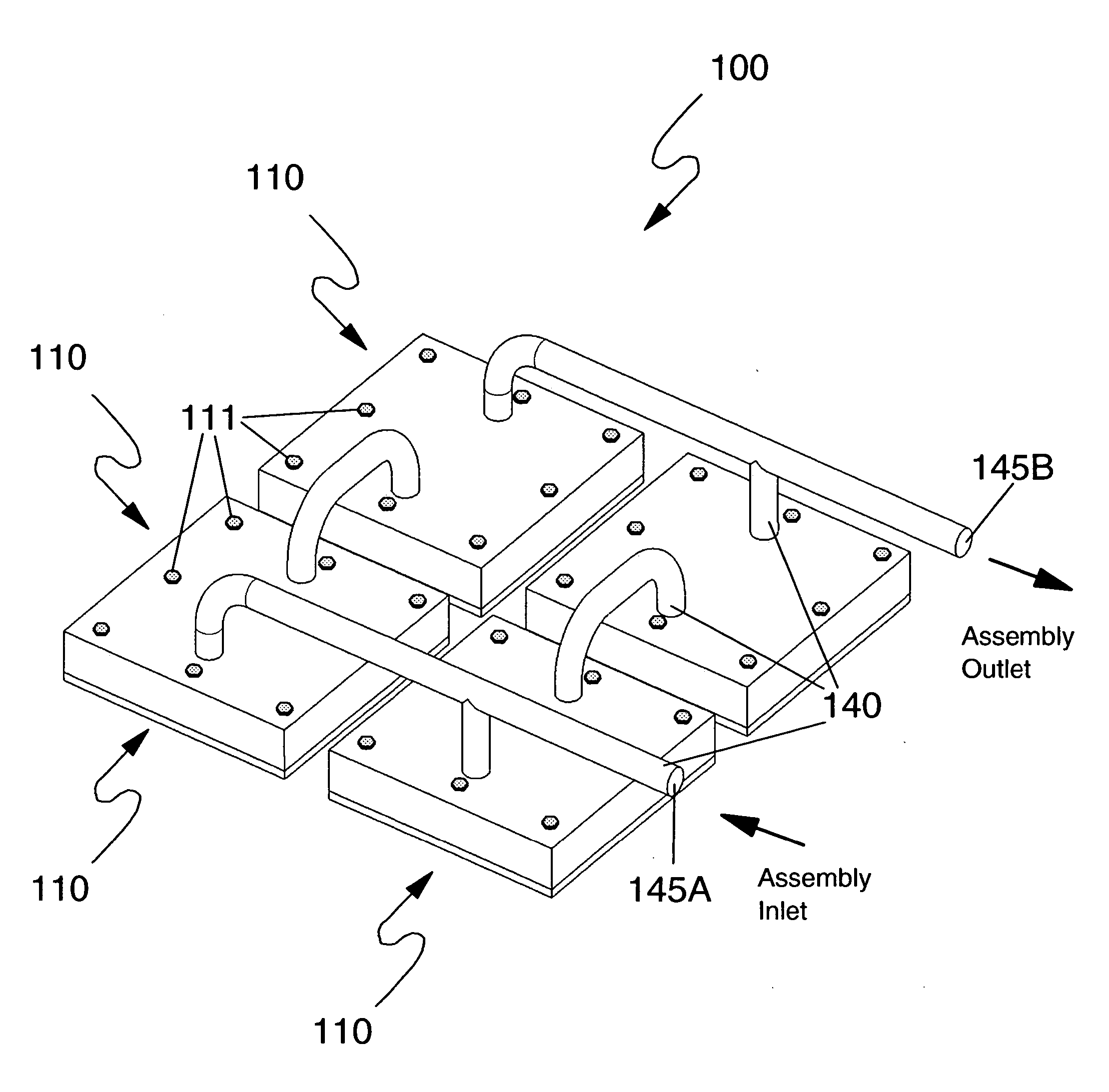
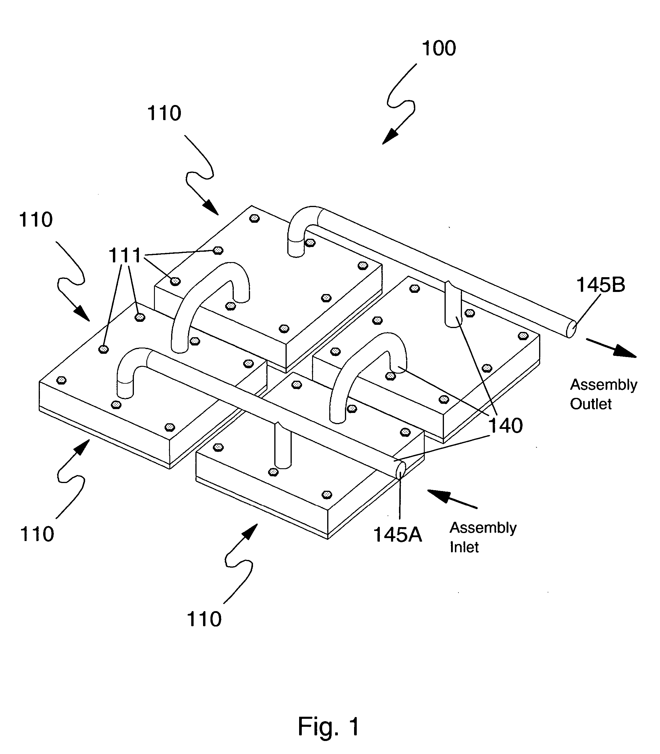
[0026]FIG. 1 illustrates a multi-cold plate fluid distribution assembly, per an embodiment of the present invention. The assembly of FIG. 1 is exemplary only; other assembly configurations are envisioned within the spirit and scope of the present invention. As illustrated in FIG. 1, a fluid distribution assembly of the present invention includes a plurality of cold plates 110: in the exemplary embodiment of FIG. 1, assembly 100 includes four cold plates 110. The teachings of the present invention are applicable to any system having two or more electronic modules: as used herein, therefore, the term plurality equates to a quantity of two or more. Assembly 100 also includes a plurality of flexible, nonmetallic conduits 140. Conduits 140 are sealably affixed to cold plates 110, thereby creating fluid dis...


PUM


Abstract

A cooling fluid distribution assembly for a plurality of electronic modules, using a composite cold plate structure. One cold plate is associated with each electronic module requiring liquid cooling. Each cold plate includes a high thermal conductivity base sealably fastened to a cover, the cover having at least one fluid inlet and at least one fluid outlet. Cover fluid inlets and outlets are connected via a plurality of flexible, nonmetallic conduits, the conduits being bonded to the cover inlets and outlets. Each cold plate cover is formed of a material that is capable of being bonded to the flexible, nonmetallic conduits, covers are therefore formed of a different material than the material comprising the cold plate base. Cold plate structures preferably include internal fluid distribution structures. The resulting cooling fluid distribution assembly provides reliable fluid connections and is sufficiently flexible to adjust for variances in module height etc.

Description

FIELD OF THE INVENTION [0001] The present invention relates in general to cooling of electronic systems. In particular, the present invention relates to a cooling fluid distribution apparatus for an electronic system having two or more fluid cooled electronic modules. BACKGROUND OF THE INVENTION [0002] As is known, operating electronic devices produce heat. This heat should be removed from the devices in order to maintain device junction temperatures within desirable limits: failure to remove the heat thus produced results in increased device temperatures, potentially leading to thermal runaway conditions. Several trends in the electronics industry have combined to increase the importance of thermal management, including heat removal for electronic devices, including technologies where thermal management has traditionally been less of a concern, such as CMOS. In particular, the need for faster and more densely packed circuits has had a direct impact on the importance of thermal mana...

Claims


Application Information

Patent Timeline
Patent Type & Authority Applications(United States)
IPC IPC(8): H01L23/473H05K7/20
CPCH01L23/473H01L2224/73253H01L2224/16
Inventor CHU, RICHARD C.ELLSWORTH, MICHAEL J. JR.SCHMIDT, ROGER R.SIMONS, ROBERT E.
Owner IBM CORP
Why Eureka
Try Eureka