Apparatus for providing broadcasting service through overlay structure in WDM-PON

Inactive Publication Date: 2005-06-16
ELECTRONICS & TELECOMM RES INST
View PDF5 Cites 68 Cited by
  • Summary
  • Abstract
  • Description
  • Claims
  • Application Information

AI Technical Summary

Benefits of technology

[0012] According to another aspect of the present invention, there is provided an apparatus for providing a broadcasting service through an overlay structure in a WDM-PON, the apparatus comprising: an arrayed-waveguide grating (AWG) demultiplexing a multiplexed signal of N data communication optical wavelength signals and a broadcasting optical wavelength signal, which have separate wavelengths, transmitted from an OLT and transmitting the demultiplexed signals to

Problems solved by technology

However, it is predicted that it is difficult to deploy commercial services on the in-band integration method in the n

Method used


Image

  • Apparatus for providing broadcasting service through overlay structure in WDM-PON
  • Apparatus for providing broadcasting service through overlay structure in WDM-PON
  • Apparatus for providing broadcasting service through overlay structure in WDM-PON

Examples


first embodiment

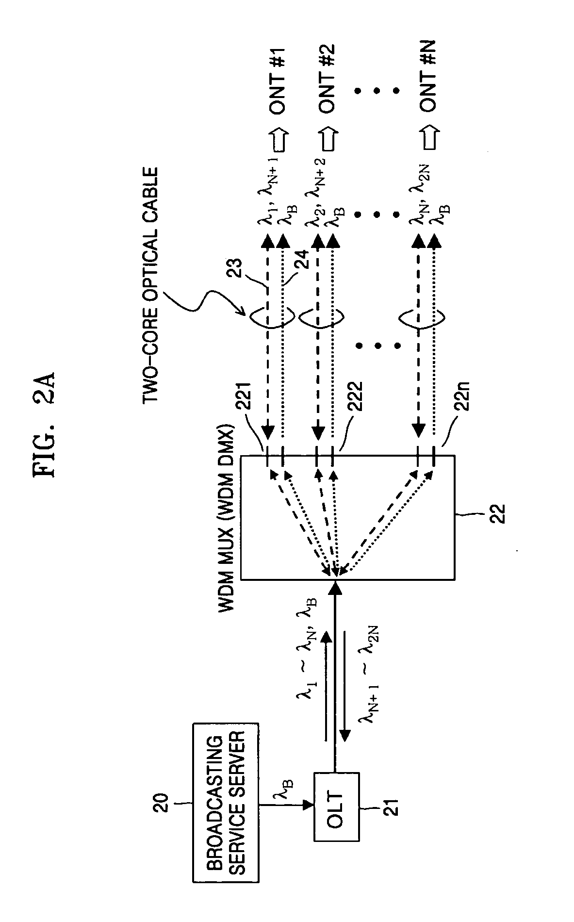
[0032]FIG. 2A is a first configuration of a WDM-PON providing a broadcasting service through an overlay structure according to the present invention.

[0033] An OLT 21 receives a broadcasting optical wavelength λB on which broadcasting signals are carried from a broadcast server 20, multiplexes the broadcasting optical wavelength λB with downstream data communication optical wavelengths λ1, . . . , λN, and transmits the multiplexed wavelengths to subscribers, i.e., an optical network terminal (ONT) #1 through an ONT #N. The broadcasting optical wavelength λB input to a WDM multiplexer / demultiplexer (MUX / DMX) 22 is split to all subscriber ports 221, 222, . . . , 22n, and the downstream data communication optical wavelengths λ1, . . . , λN are transmitted to relevant subscribers by being wavelength-demultiplexed and transferred to relevant subscriber ports.

[0034] Upstream data communication optical wavelengths λN+1, . . . , λ2N on which upstream data input from ONTs are carried are mul...

second embodiment

[0040]FIG. 2C illustrates in detail another example of the WDM MUX (WDM DMX) 22 shown in FIG. 2A according to the present invention.

[0041] A configuration shown in FIG. 2C adopts an arrayed-waveguide grating (AWG). Data communication optical wavelengths λ1, . . . , λN and a broadcasting optical wavelength λB are demultiplexed by the AWG and transmitted to subscriber ports, and data communication optical wavelengths λN+1, . . . , λ2N are multiplexed by the AWG and transmitted to the OLT 21. Here, since multiplexing and demultiplexing must be performed using one AWG, a free spectral range of the AWG is matched to using wavelength bands λ1, . . . , λN and λB. If it is assumed that a grating order corresponding to the data communication optical wavelengths λN+1, . . . , λ2N is m, a grating order corresponding to the data communication optical wavelengths λ1, . . . , λN is m−1.

[0042] After a signal focused on a λB focal position to split the broadcasting optical wavelength λB to λB outp...

third embodiment

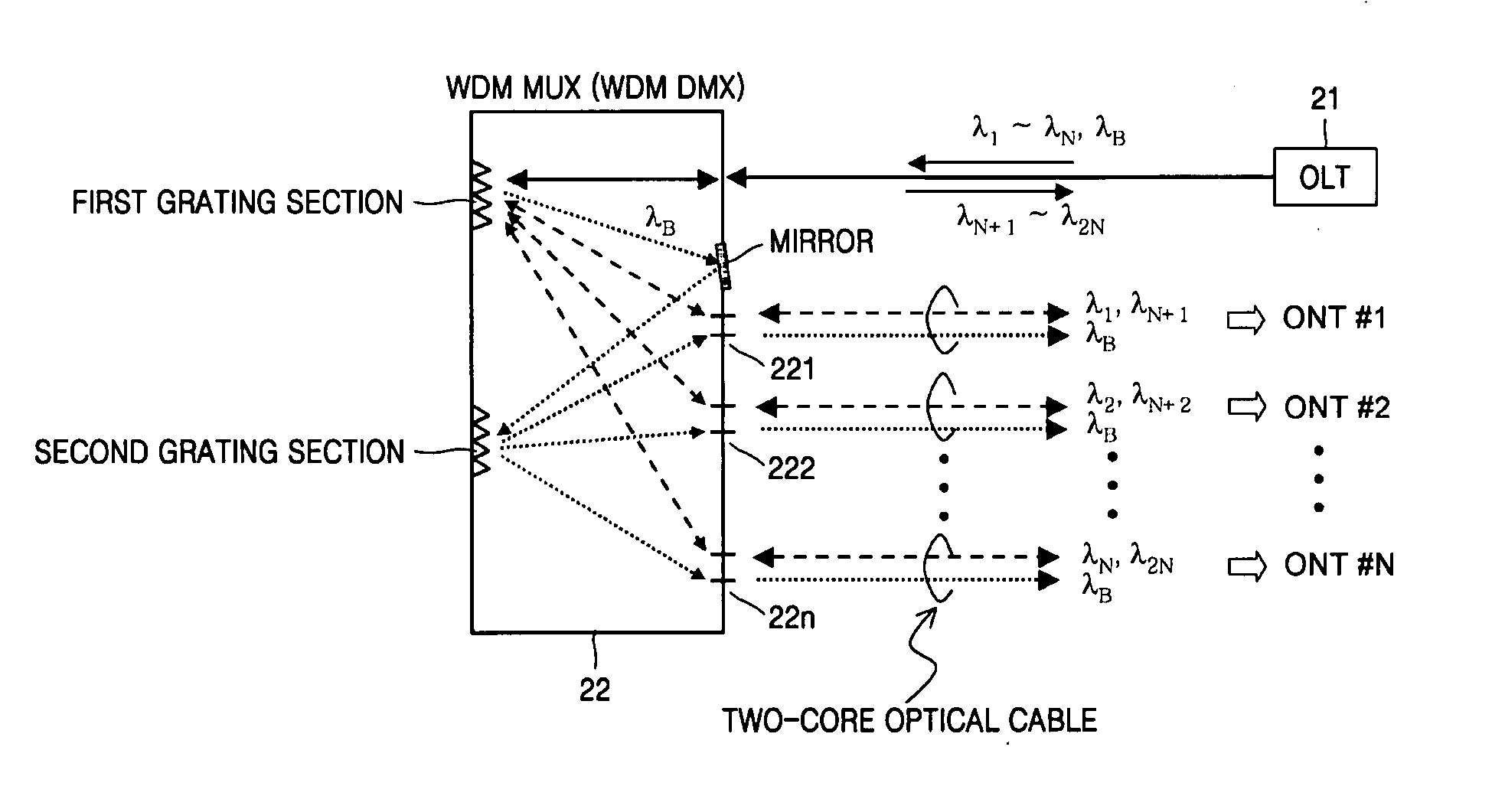
[0046]FIG. 3B illustrates in detail an example of the WDM MUX (WDM DMX) 22 shown in FIG. 3A according to the present invention.

[0047] Input multiplexed optical wavelengths λ1, . . . , λN and λB are wavelength-demultiplexed by a first grating section. The data communication optical wavelengths λ1, . . . , λN are directly transmitted to relevant subscriber ports. The broadcasting optical wavelength λB is diffracted by the first grating section and reflected to a third grating section by a mirror. The reflected broadcasting optical wavelength λB is split(copied) to all subscriber ports by the third grating section.

[0048] Upstream data communication optical wavelengths λN+1, . . . , λ2N are input from ONTs, wavelength-multiplexed by a second grating section, and transmitted to an OLT 21 via a single-core optical cable.


PUM


Abstract

Provided is an apparatus for providing a broadcasting service through an overlay structure in a WDM-PON. The apparatus comprises: a first grating section receiving a multiplexed signal of N data communication optical wavelength signals and a broadcasting optical wavelength signal, which have separate wavelengths, transmitted from an optical line terminal (OLT) and wavelength-demultiplexing the multiplexed signal; a mirror reflecting the broadcasting optical wavelength signal wavelength-demultiplexed by the first grating section; and a second grating section receiving the reflected broadcasting optical wavelength signal and splitting it to all subscriber ports.

Description

[0001] This application claims the priority of Korean Patent Application Nos. 2003-89360, filed on Dec. 10, 2003 and 2004-74217, filed on Sep. 16, 2004 in the Korean Intellectual Property Office, the disclosures of which are incorporated herein in their entirety by reference. BACKGROUND OF THE INVENTION [0002] 1. Field of the Invention [0003] The present invention relates to an apparatus for providing a broadcasting service through an overlay structure in a wavelength division multiplexing passive optical network (WDM-PON). [0004] 2. Description of the Related Art [0005] Since a WDM-PON system allocates a wavelength per user, the WDM-PON system is expected as a system suitable to provide a next generation fiber to the home (FTTH) service, which has a flexibility for various information services provided to each user. [0006] The WDM-PON system has advantages as follows: 1) it is possible to provide a high speed service of more than 1 Gbps to each user since a dedicated wavelength is ...

Claims


Application Information

Patent Timeline
IPC IPC(8): G02B6/34H04H1/00H04H20/69H04J14/02
CPCG02B6/12019G02B6/2931G02B6/29313H04H20/69H04J14/0226H04J14/0227H04J14/0232H04J14/0234H04J14/0238H04J14/0246H04J14/0247H04J14/025H04J14/0252
Inventor KIM, BYOUNGCHO, SEUNGLEE, HYEONG
Owner ELECTRONICS & TELECOMM RES INST
Why Eureka
Try Eureka