One-way clutch

Active Publication Date: 2005-06-16
NIFCO INC
View PDF4 Cites 16 Cited by
  • Summary
  • Abstract
  • Description
  • Claims
  • Application Information

AI Technical Summary

Benefits of technology

[0006] According to a second aspect of the present invention, a holding member is provided for supporting the planet gear together with the inner member in an axial direction. Further, an axial portion is provided in the planet gear, and is supported in a bearing hole elongated in a circumferential direction and provided in at least one of the holding member and the inner member. The elongated hole regulates the moving range of the planet gear.
[0007] In the present invention, when

Problems solved by technology

Accordingly, a tip of the teeth of the planet gear contacts an inner circumferential surface of the depression, thereby causing a

Method used


Image

  • One-way clutch
  • One-way clutch
  • One-way clutch

Examples


Example

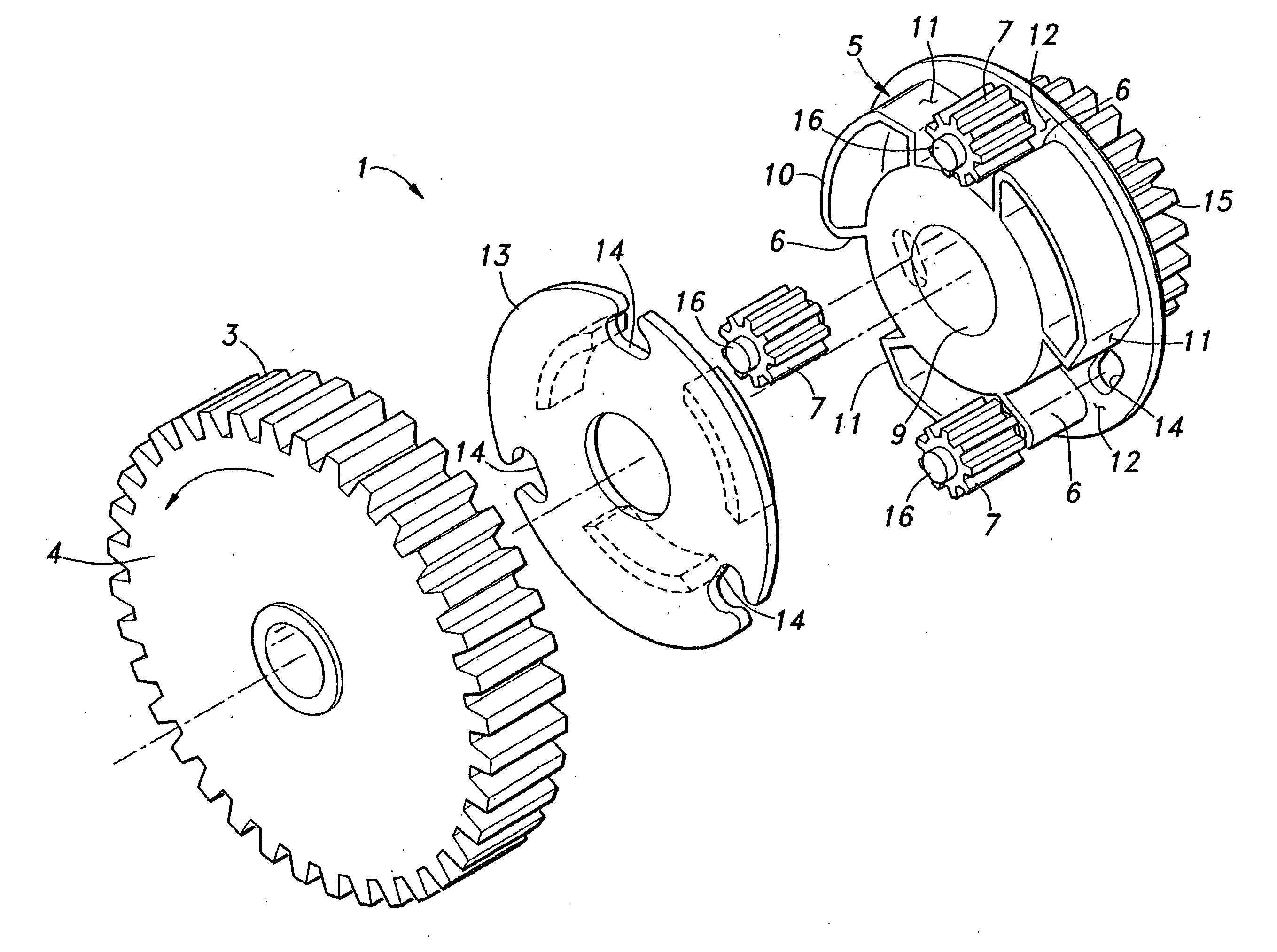
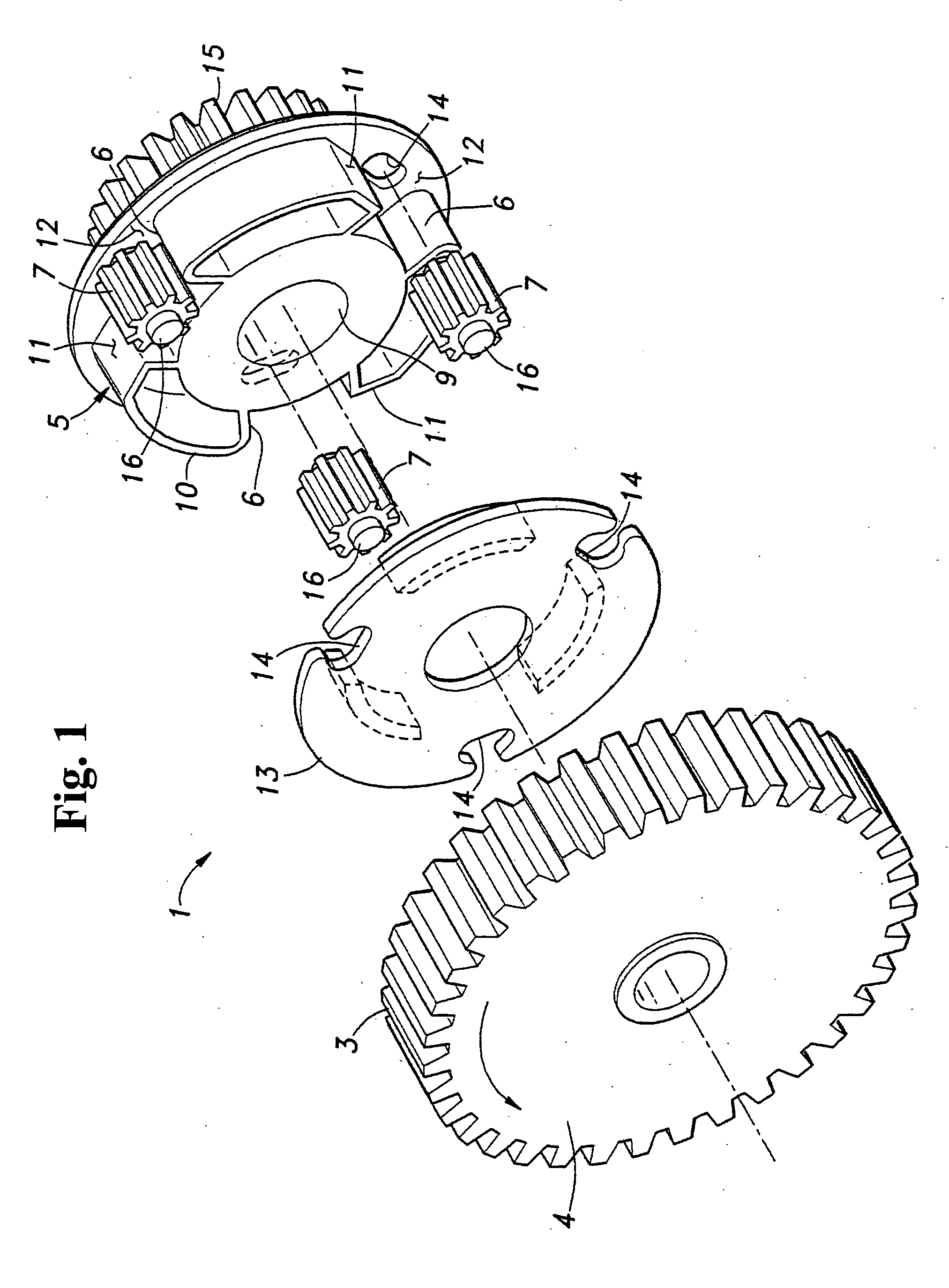
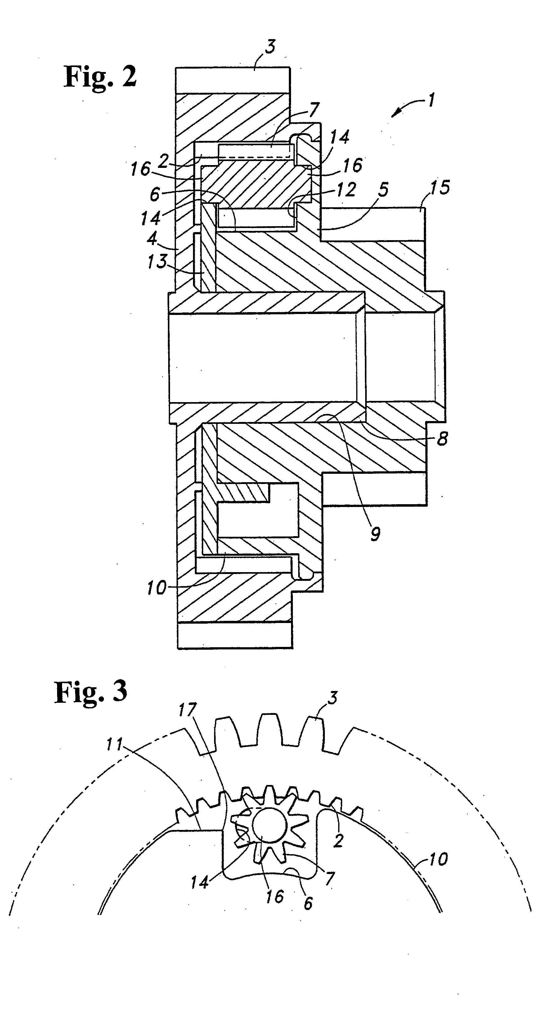
[0011] Hereunder, embodiments of the present invention will be explained with reference to the attached drawings. FIG. 1 is an exploded perspective view showing components of a one-way clutch according to an embodiment of the present invention. FIG. 2 is a cross sectional view of the one-way clutch in an assembled state. A one-way clutch 1 is formed of a cylindrical outer member 4 with a shallow bottom having circular teeth 2 and 3 formed on an inner circumferential surface and an outer circumferential surface thereof, respectively; an inner member 5 retained in the inner teeth 2 of the outer member 4; and three planet gears 7 loosely retained in depressions 6 formed in the outer circumferential surface of the inner member 5 at equally divided three positions in a circumferential direction and having a rectangular shape viewed from an axial direction.

[0012] The outer member 4 and the inner member 5 are supported by an axis (not shown) in a state wherein a boss portion 8 formed at t...


PUM


Abstract

A one-way clutch includes an outer member with inner teeth; an inner member rotatably retained in the outer member concentrically with the same and having a depression formed in an outer circumference thereof; at least one planet gear loosely and rotatably retained in the depression and engaging the inner teeth; and a removed portion formed in the outer circumference of the inner member adjacent the depression. When the inner member rotates in one direction with respect to the outer member, the planet gear freely rotates inside the depression. When the inner member rotates in an opposite direction with respect to the outer member, a part of teeth of the planet gear engages the removed portion. The planet gear is retained in the depression via a moving-range regulating member for regulating a moving range of the planet gear in radial and circumferential directions.

Description

BACKGROUND OF THE INVENTION AND RELATED ART STATEMENT [0001] The present invention relates to a one-way clutch, especially, a one-way clutch suitable for preventing a driven side from being driven in reverse by a driving side. [0002] In a carriage of a copy machine, for example, a one-way clutch is provided between a paper-path roller and a drive motor in order to remove a paper smoothly upon a paper jam. Such a one-way clutch includes: an outer member with inner teeth; an inner member retained in the outer member to be rotatable concentrically with the same and including a depression on an outer circumference surface thereof; and a planet gear rotatably retained in the depression for engaging the inner teeth. When the outer member is driven, a tip of a part of teeth of the planet gear engages an edge of a removed portion formed in the outer circumferential surface of the inner member at a portion adjacent to the depression. Accordingly, the outer member is connected to the inner me...

Claims


Application Information

Patent Timeline
IPC IPC(8): F16D41/00F16H35/00F16D41/06F16D41/18
CPCF16D41/18F16D41/06
Inventor JINBO, NAOTO
Owner NIFCO INC
Why Eureka
Try Eureka