Hair removing device with a lotion applicator

a technology of lotion applicator and hair removal device, which is applied in the direction of packaging foodstuffs, packaging goods, transportation and packaging, etc., can solve the problems of lotion being too much or too little for users with different skin characteristics or preferences, and achieve the effect of reducing thickness and preventing lotion from leakag

Inactive Publication Date: 2005-06-16
MATSUSHITA ELECTRIC WORKS LTD
View PDF10 Cites 5 Cited by
  • Summary
  • Abstract
  • Description
  • Claims
  • Application Information

AI Technical Summary

Benefits of technology

[0019] Further, the present invention discloses a unique feature of avoiding the leakage of the lotion from the tank itself prior to the tank being coupled to the tank conduit or the lotion feed path. For this purpose, the tank has a spout which is detachable to the lotion feed path and provided with a normally closed elastic valve. The elastic valve is caused to deform elastically to open for discharging the lotion to the lotion feed path only when the spout is coupled to the lotion feed path.
[0020] The elastic valve has a thick member and a thin member surrounding the thick member and giving elasticity to the valve. The thin member is supported to the spout and is provided with a vent for passing therethrough the lotion. The spout includes a socket hole of circular cross-section for detachably receiving therein a tube forming the lotion feed path. The thick member is formed into a semi-spherical shape with a rounded portion being pressed against the end of the socket hole to close the same in the absence of the tube in the socket hole. Thus, the rounded portion of the semi-spherical shaped thick member is utilized to close the spout successfully for preventing the lotion leakage.
[0021] Preferably, the tank is formed into a flat flexible bag having a reduced thickness relative to its width. In this connection, the spout is formed with restricting means adjacent to the elastic valve in order to restrict an external force being applied in the thickness direction of the bag from transmitting to and deforming

Problems solved by technology

The device is designed to dispense the lotion at a constant rate, which poses a problem that th

Method used


Image

  • Hair removing device with a lotion applicator
  • Hair removing device with a lotion applicator
  • Hair removing device with a lotion applicator

Examples


first embodiment 1 to 12

First Embodiment 1 to 12>

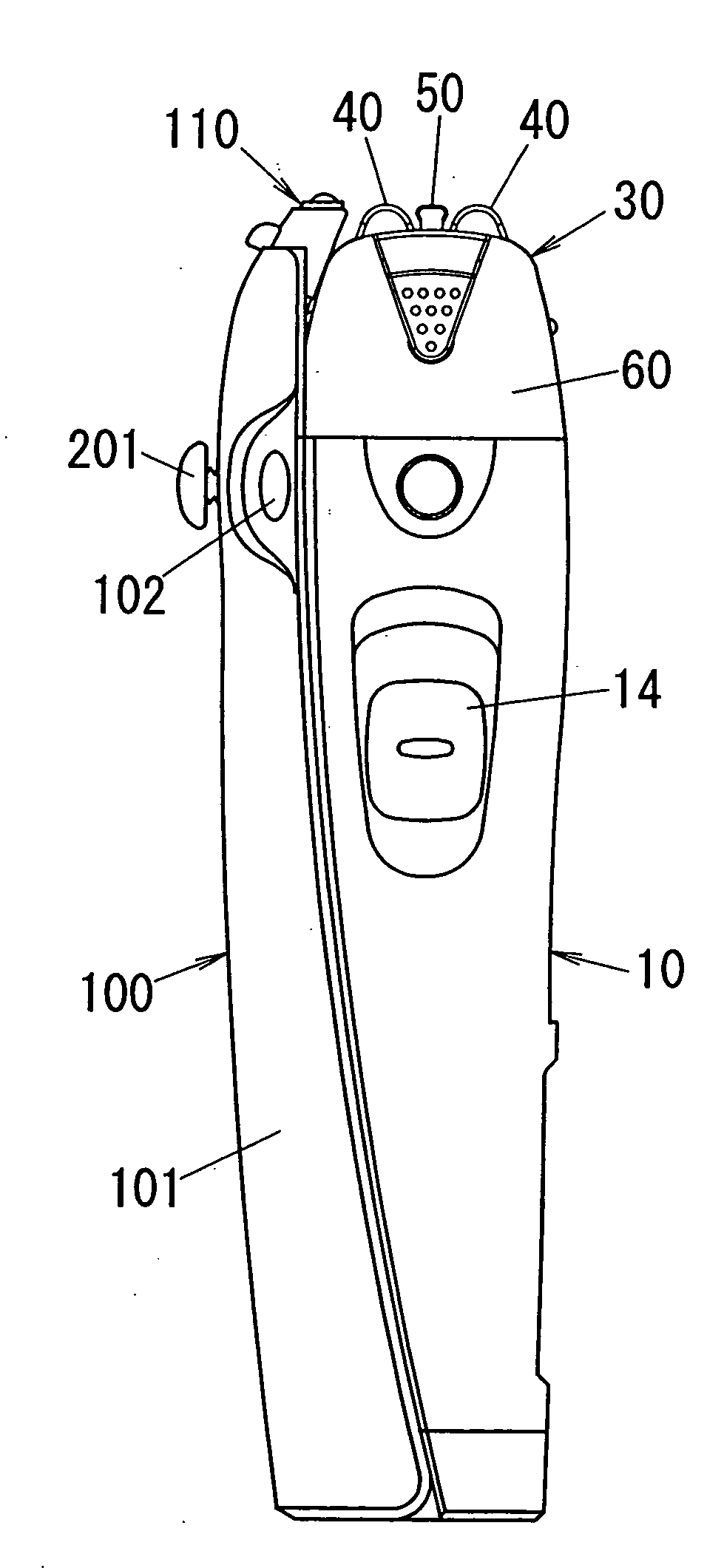
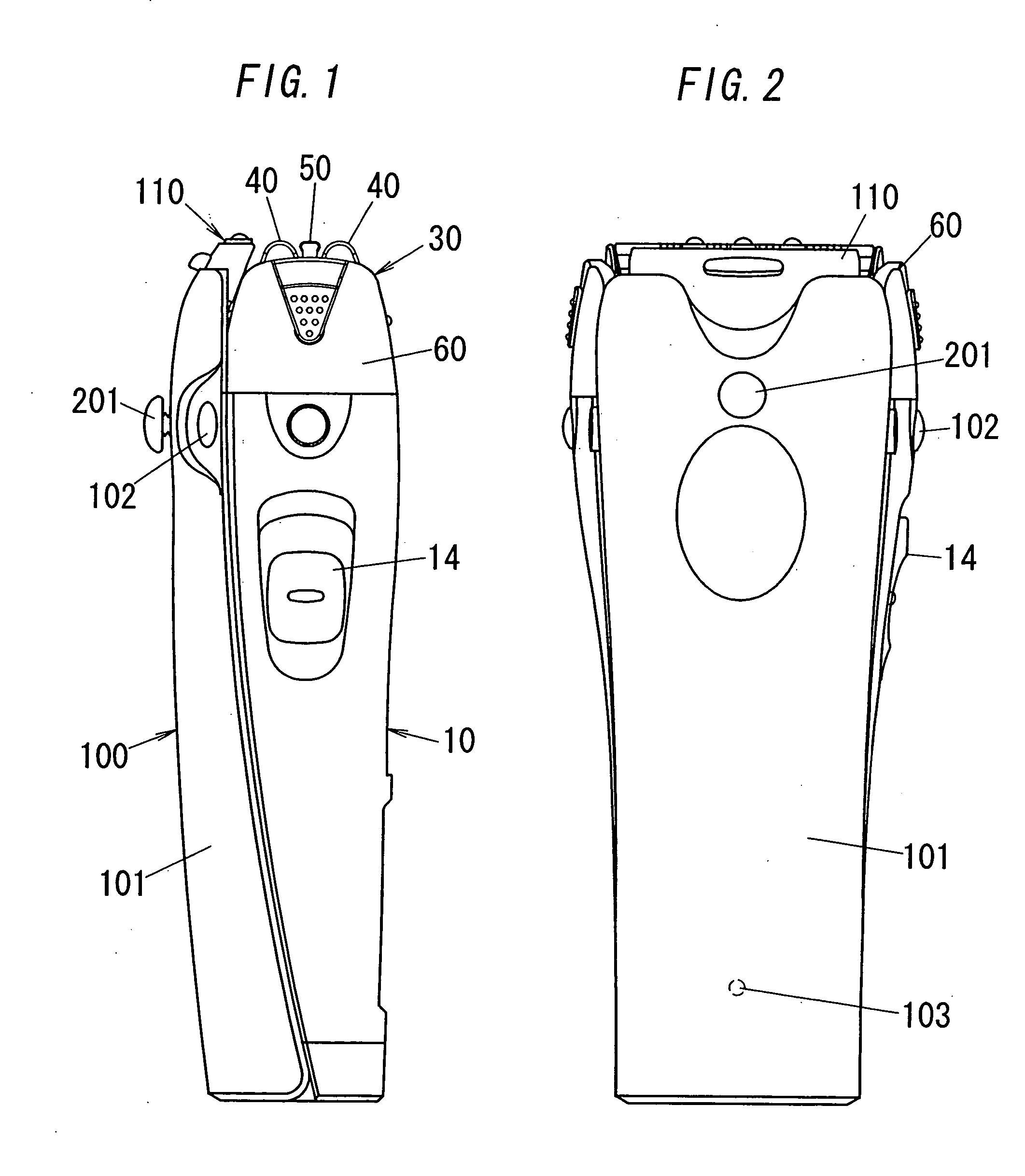
[0067] Referring now to FIG. 1, there is shown a dry shaver as one typical version of the personal hair removing device in accordance with the first embodiment of the present invention. The shaver includes a housing 10 to be grasped by a hand of a user, a shaving head, i.e., a hair removing head 30 projecting on top of the housing, and an applicator 110 projecting adjacent to the hair removing head 30 for dispensing a lotion on a user's skin where the hair removing is made.

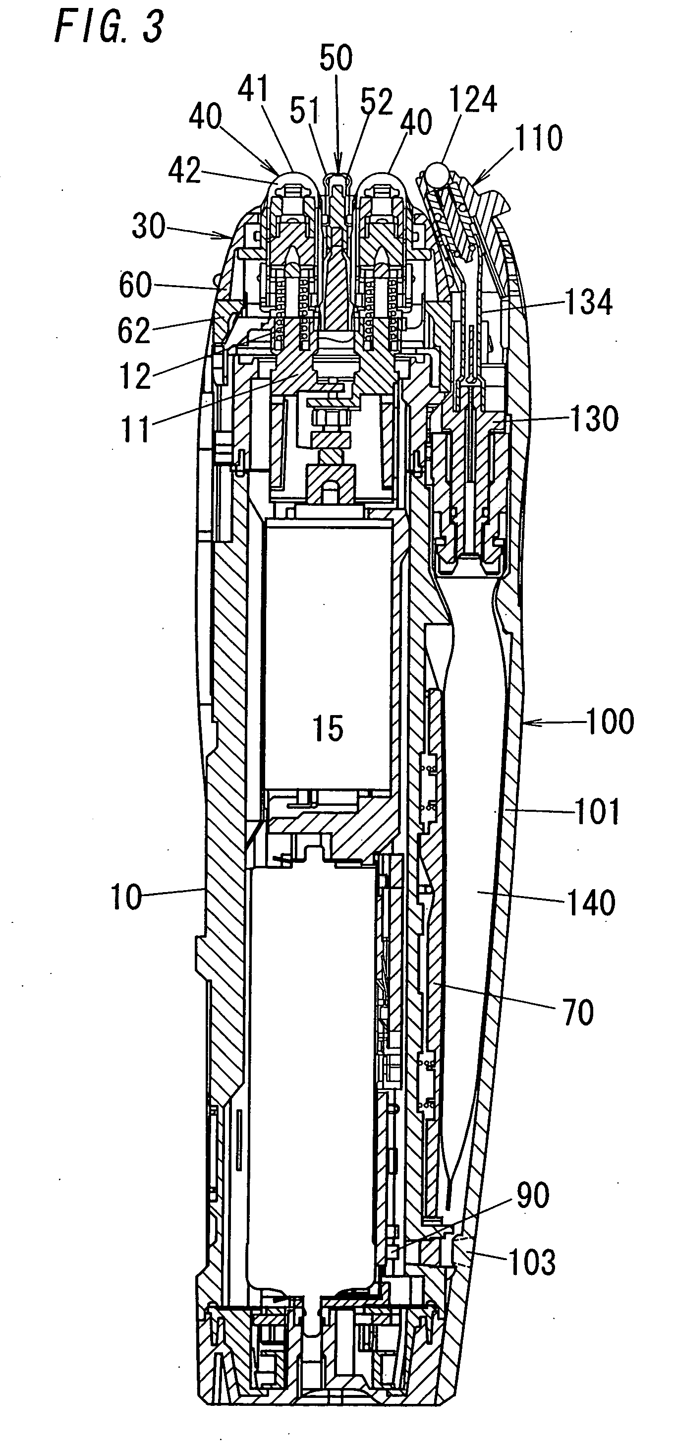
[0068] The hair removing head 30 is composed of three hair cutting sections, namely, a pair of short-hair cutters 40 and a long-hair cutter 50 interposed between the short-hair cutters 40. The short-hair cutter 40 has a U-shaped outer shearing foil 41 and an inner cutter 42 which is driven to oscillate in shearing engagement with the foil, while the long-hair cutter 50 is composed of a slender outer cutter 51 and an inner cutter 52 driven to oscillate in shearing engagement with the outer...

second embodiment 15

Second Embodiment 15>

[0078]FIG. 15 illustrates a second embodiment of the present invention in which the pressurizer 70 is made to vary its pressing force to the tank 140 for regulating the dispensing amount of the lotion. The other structures and the functions are identical to the first embodiment so that no duplicate explanation is made here and like parts are designated by like reference numerals. In this embodiment, the spring-loaded pusher 83 urging the pressurizer 70 is cooperative with a handle 203 to constitute a regulating means or system for regulating the dispensing amount of the lotion. As shown in FIGS. 6 and 15, the pusher 83 comprises a pair of coil springs 85 fitted respectively around vertical rods 86 secured to the housing 10, and a pair of sliders 87 connected to the upper end of the coil springs 85. The sliders 87 are slidable along the length of the respective rods 86 and are each provided with a pivot arm 88 having one end pivotally connected to the slider and ...

third embodiment 16

Third Embodiment 16>

[0079]FIG. 16 illustrates a third embodiment of the present invention in which the tank 140 receives an additional pressing force by a manual compressor 210 which constitutes a regulating system for regulating the dispensing amount of the liquid from the applicator 110. The other structures and the functions are identical to the first embodiment so that no duplicate explanation is made here and like parts are designated by like reference numerals. The compressor 210 comprises a frame 211 secured to the front cover 101 and carrying a handle 212 with a knob 213, a pad 214, aid a spring 215 urging the handle 212 away from tank 140. The pad 214 extends through the front cover 101 to come into pressing contact with the tank 140 to give an additional pressure for squeezing the tank 140 independently of the pressurizer 70. Thus, the manual compressor 210 develops the squeezing force that varies with the pressing force applied to the knob 213 by the user, thereby enablin...


PUM


Abstract

An improved hair removing device is capable of controlling a dispensing amount of the lotion to give the lotion adequately as intended by a user for comfortable hair treatment. The device includes a housing carrying a hair removing head adapted to be held against a user's skin for hair depilation or epilation. The device further includes an applicator for dispensing the lotion on the user's skin, a tank holding the lotion, and a lotion supply mechanism for supplying the lotion from the tank to the applicator. The lotion supply mechanism is provided with a regulating means which regulates an amount of the lotion being dispensed from the applicator.

Description

TECHNICAL FIELD [0001] The present invention is directed to a hair removing device with a lotion applicator, and more particularly to the personal hair removing device capable of dispensing a lotion for facilitating the hair treatment as well as for making a skin care. BACKGROUND ART [0002] WO98 / 08661 and Japanese Utility Model Publication No. 59-108574 disclose a portable hair removing device capable of dispensing a lotion for facilitating the hair removal. The device incorporates a pump which is activated by a button or switch to feed the lotion over a user's skin where the hair removal is intended. The device is designed to dispense the lotion at a constant rate, which poses a problem that the lotion may be too much or too less for users of different skin characteristics or preferences. DISCLOSURE OF THE INVENTION [0003] In view of the above inconvenience, the present invention has been achieved to provide an improved hair removing device which is capable of controlling a dispens...

Claims


Application Information

Patent Timeline
IPC IPC(8): A45D26/00A45D33/02A45D34/04B26B19/40
CPCA45D26/0028A45D34/041B26B19/40A45D2026/0095A45D2026/009A45D26/00
Inventor SAITO, ATSUHIROKATO, HIROKAZUIWASAKI, JYUZAEMONTANAKA, HIDEKIYANAGI, KOUTAROUUEDA, YASUNORITSUSHIO, TOSHIYUKIYAMASAKI, MASANOBUURANO, YOUJIKITAHARA, HARUNORI
Owner MATSUSHITA ELECTRIC WORKS LTD
Why Eureka
Try Eureka