Piston type aircraft engine

a technology of aircraft engine and propeller, which is applied in the direction of piston type power plants, mechanical devices, fuel injection devices, etc., can solve the problems of the engine that was developed for use, the engine that is not suitable for use in modern light and ultralight airplanes, and the use of v-type engines in modern aircraft provides challenges

Inactive Publication Date: 2005-06-23
FUERLINGER JOSEF +2
View PDF99 Cites 19 Cited by
  • Summary
  • Abstract
  • Description
  • Claims
  • Application Information

AI Technical Summary

Problems solved by technology

However, the use of V-type engines in modern aircraft provide challenges due to their size and shape, among other reasons.
As would be appreciated by those skilled in the art, most, if not all, of the engines that were developed for use in World War II aircraft are not suitable for use in modern light and ultralight airplanes due to their large size, weight, and power.
As such, these aircraft are not suited to accept the engines designed for World War II fighters, bombers, and other aircraft for the simple reason that the engines developed during World War II were enormous in size, by comparison with their counterparts that are manufactured and sold for the private aircraft market.
These engines, as mentioned, are quite large and heavy, and produce too much horsepower for light and ultralight aircraft.
However, a sudden drop in altitude can create a condition known as shock cooling which can cause the engine block to crack.
One unfortunate side-effect of this design is that, if the exhaust system is not perfectly maintained, leaking carbon monoxide (CO) can become entrained in the heated air before being vented into the passenger cabin.
If the CO concentration becomes too high, the pilot and passengers may suffer from anoxia, which could have disasterous consequences, especially if the pilot and passengers loose consciousness during flight.
Engines that are designed for automotive applications are not suitable for use in aircraft, for a number of reasons.
Also, because these engines are used in small aircraft, weight is an issue.
Among other reasons, because car engines are not designed for high altitude (greater than 10,000 feet) use, because they are heavy, and because they are not designed to operate at 100% of rated speed for extended periods of time, car engines are not designed for aircraft use.
This redundancy necessarily adds weight to the engine.
However, each of these known attempts to design a commercially-viable engine have been unsuccessful.

Method used


Image

  • Piston type aircraft engine
  • Piston type aircraft engine
  • Piston type aircraft engine

Examples


Embodiment Construction

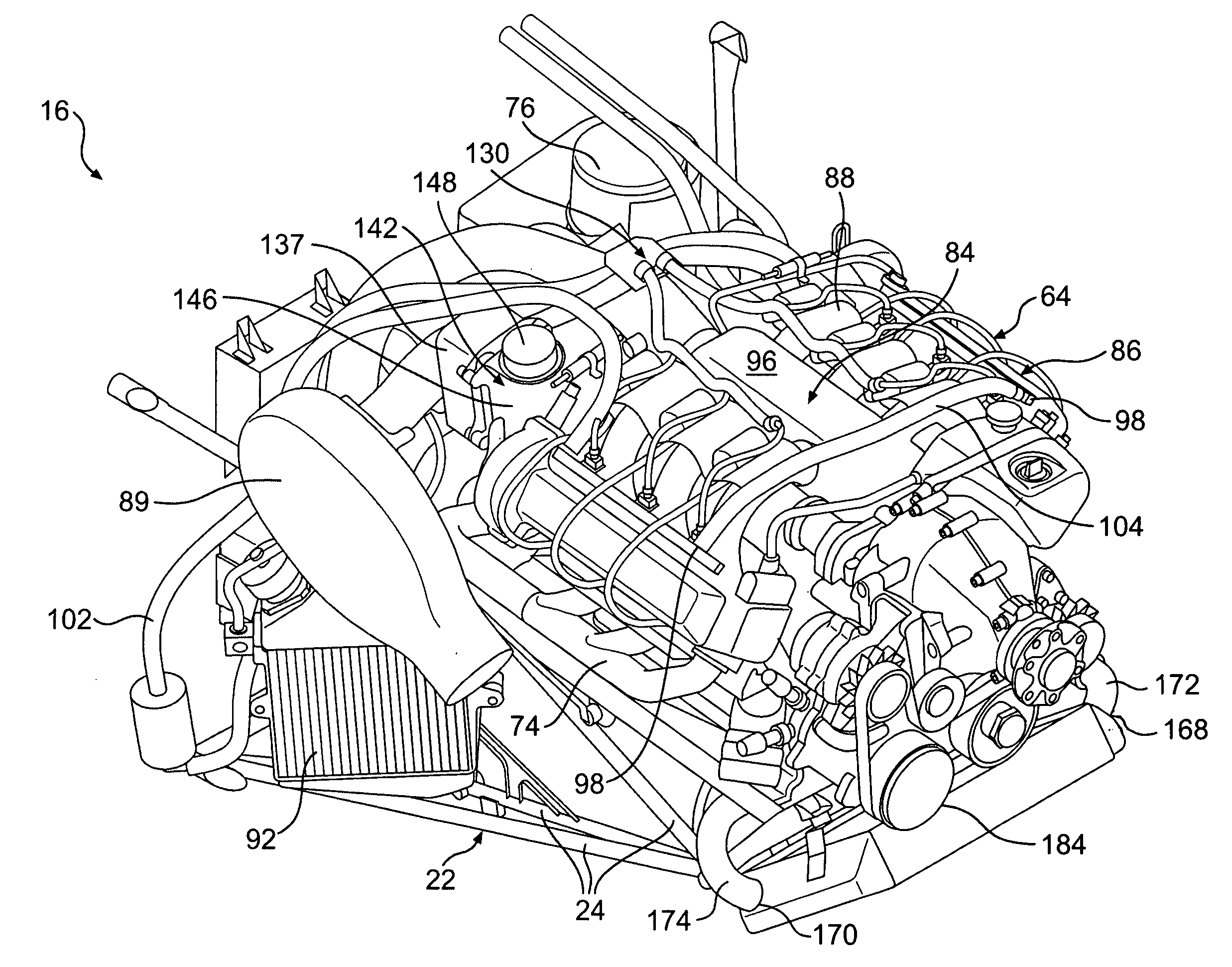
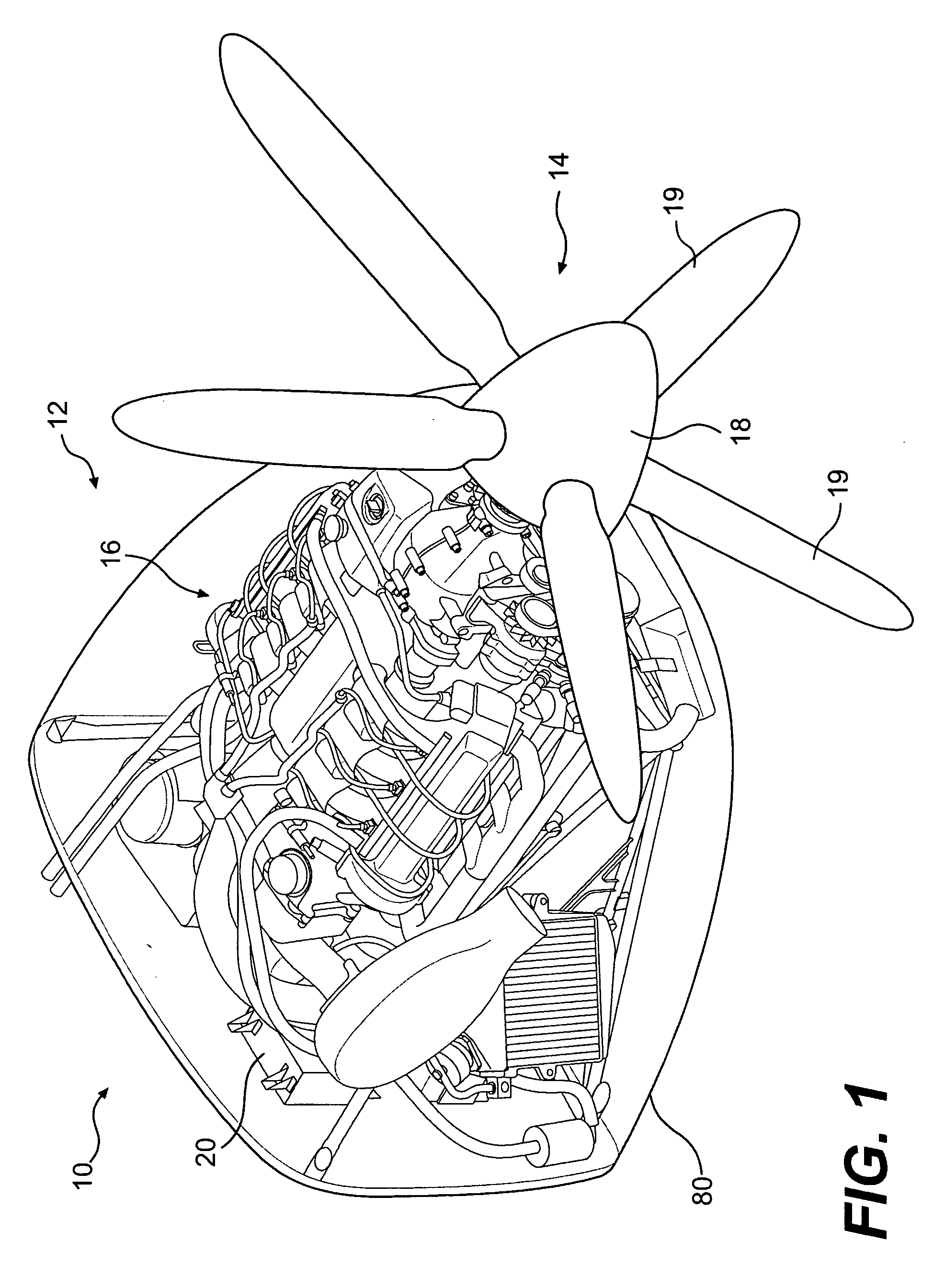
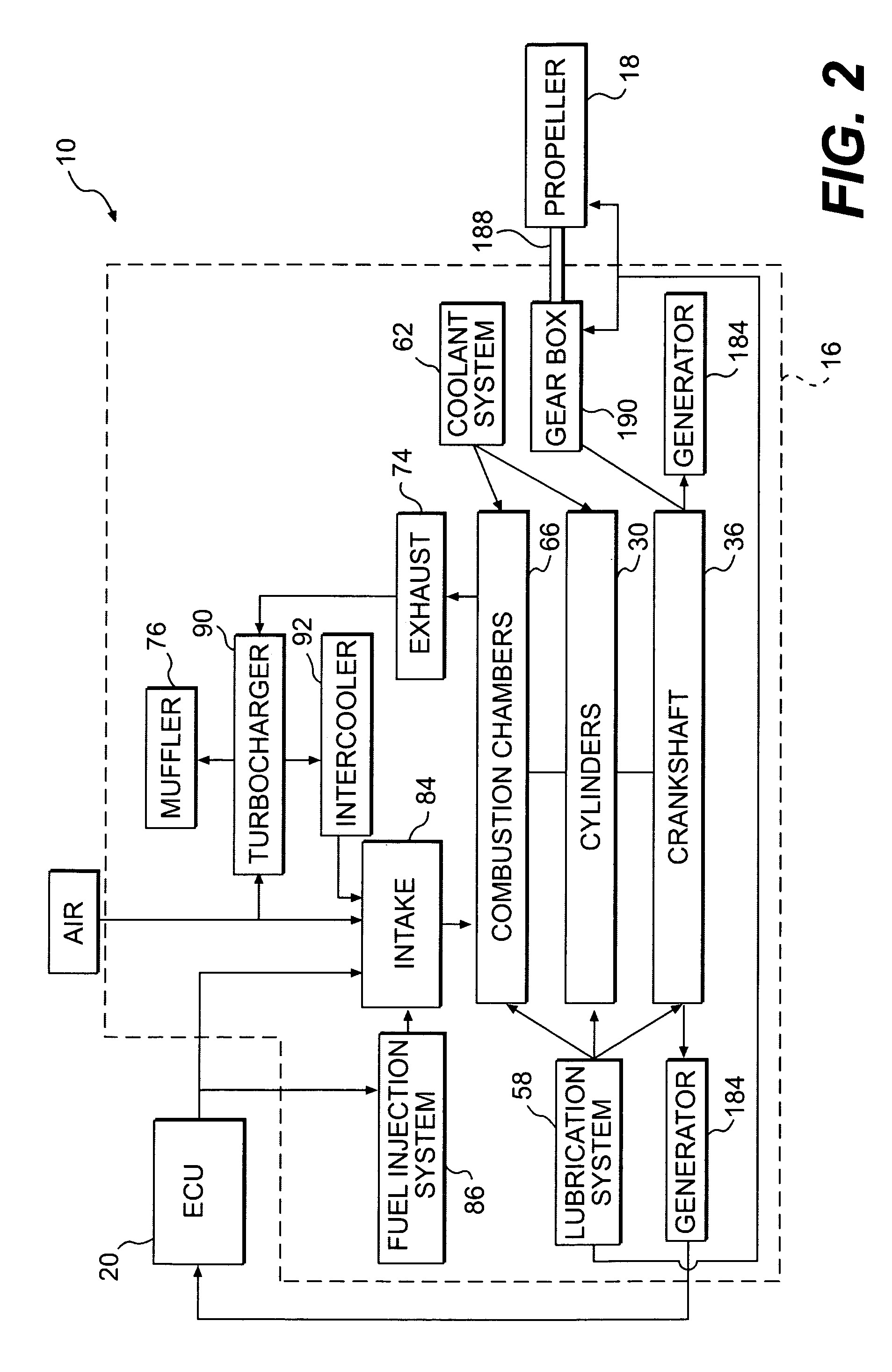
[0052]FIGS. 1 and 2 show at least one embodiment of a propulsion assembly 10 of the present invention. As shown in FIG. 1, the propulsion assembly 10 is suitable for placement in an aircraft 12 for propelling the aircraft 12. Only a front portion 14 (or nose) of the aircraft 12 is shown. In the preferred embodiment, the aircraft 12 is a light or ultralight airplane, preferably of the privately-owned type. Of course, the present invention is not limited to use with a light or ultralight aircraft. As should be appreciated by those skilled in the art, the invention may be used in any suitable aircraft, whether large or small, privately or commercially owned. The wide variety of aircraft for which the invention is designed lend to the broad scope of the invention.

[0053] The propulsion assembly 10 includes an internal combustion engine 16, a propeller shaft 188 that is operatively connected to the engine 16, and an electronic control unit (“ECU”) 20 that is electrically connected to the...


PUM


Abstract

A propulsion assembly for propelling an aircraft is disclosed. The assembly includes a four stroke internal combustion engine, a propeller shaft that is operatively connected to the engine, and an electronic control unit that is connected to the engine and is configured to monitor and control at least one operating parameter of the engine. The engine includes two to twelve cylinders having a total displacement of less than 19.6 liters, and a crankshaft that is operatively connected to the cylinders. The crankshaft rotates at a speed of at least 3,000 rpm when the engine is operating under normal conditions. The engine also includes a closed loop liquid cooling system and a fuel injection system. The engine has a total power output of 140 to 600 hp, and a total wet installed weight of less than 1.1 kg / hp. The engine meets current RTCA DO-160d, RTCA DO-178b, and US FAA FAR33 guidelines.

Description

CROSS-REFERENCE TO RELATED APPLICATIONS [0001] This application is a Continuation-In-Part of U.S. patent application Ser. No. 10 / 071,233, entitled “VIBRATION DAMPER FOR AIRCRAFT ENGINE,” which was filed on Feb. 11, 2002, and is currently pending. That application relies on priority from U.S. Provisional Application Ser. No. 60 / 331,380, which was filed on Nov. 14, 2001, and U.S. Provisional Application Ser. No. 60 / 341,874, which was filed on Dec. 21, 2001. This application is related to U.S. patent application Ser. No. 10 / 787,247, entitled “A POP-OFF VALVE FOR AN AIRCRAFT ENGINE HAVING A TURBOCHARGER CONTROL SYSTEM AND PROPELLER CONTROL SYSTEM BY A STEPPER MOTOR,” which was filed on Feb. 27, 2004, and is currently pending. This application is also related to U.S. patent application Ser. No. 09 / 566,946, entitled “CRANKCASE FOR A COMBUSTION ENGINE,” which was filed on Oct. 28, 1998, and was granted on Jul. 3, 2001 as U.S. Pat. No. 6,253,726. The contents of all five applications are in...

Claims


Application Information

Patent Timeline
Patent Type & Authority Applications(United States)
IPC IPC(8): B64D27/04F16F15/173
CPCB64D27/04F02B37/00F02B61/04F02B75/22Y10T74/2184F02M63/0295F16F15/173Y02T50/44Y02T10/144F02B2075/027Y02T10/12Y02T50/40
Inventor FUERLINGER, JOSEFLIPPITSCH, HEINZBAYERL, JOHANN
Owner FUERLINGER JOSEF
Why Eureka
Try Eureka