In addition, for many applications, it is difficult and costly to provide sufficient current for a
large array.
One complication in
DC resistivity measurement arises when the sub-bottom (e.g., beneath the sea floor) is layered.
The implementation of such an array is logistically difficult because significant lengths of cables must be moved for each individual measurement.
However, the actual data collection and analysis to derive the
resistivity distribution is limited by the underlying
physics and the practical considerations of making measurements (e.g., spacing and cable length).
Except for surveys to recover the resistivity of shallow depths, such arrays of current and potential electrodes are impractical (uneconomic) on land, but practical and feasible on the
sea bottom as described herein.
Unfortunately, this discrete sampling approach is not satisfactory if the near surface is highly inhomogeneous.
This results in static offsets that
pose significant problems in interpreting the MT data.
Unfortunately dense coverage on land is often precluded by practical problems of access, powerline
noise, habitation etc.
This type of MT
system typically relies on acoustic positioning in
deep water, and, thus, may suffer from positioning errors.
If the secondary fields are small, it may be technically difficult to measure them in the
frequency domain because of the presence of much larger
primary field.
Although the inhomogeneity in the formation may create higher wave numbers from the natural fields, such low order wave number field cannot provide coverage as wide as that provided by the
controlled source.
A thin resistive layer can
pose a difficult problem for MT measurements because it can reduce
signal magnitudes beyond detection by MT as the layer resistivity increases.
Thus, while a thin resistive layer may
pose a problem for measurements using DC or
low frequency sources (e.g., MT), it poses little problem for measurements using
high frequency sources (e.g., CSEM).
The cost of creating arrays of such transmitters on land is uneconomical.
However, interpretation of subsurface features based on multiple measurements from a single large source often leads to ambiguities that render the method useless.
Nevertheless, these systems provide a lesson, albeit costly, on the importance of wide spatial coverage for both transmitters and receivers.
The insights gained from surface CSEM systems are not applicable and the inverted boundary conditions alter the sensitivity of the fields to the sub-bottom resistivity as they do for MT.
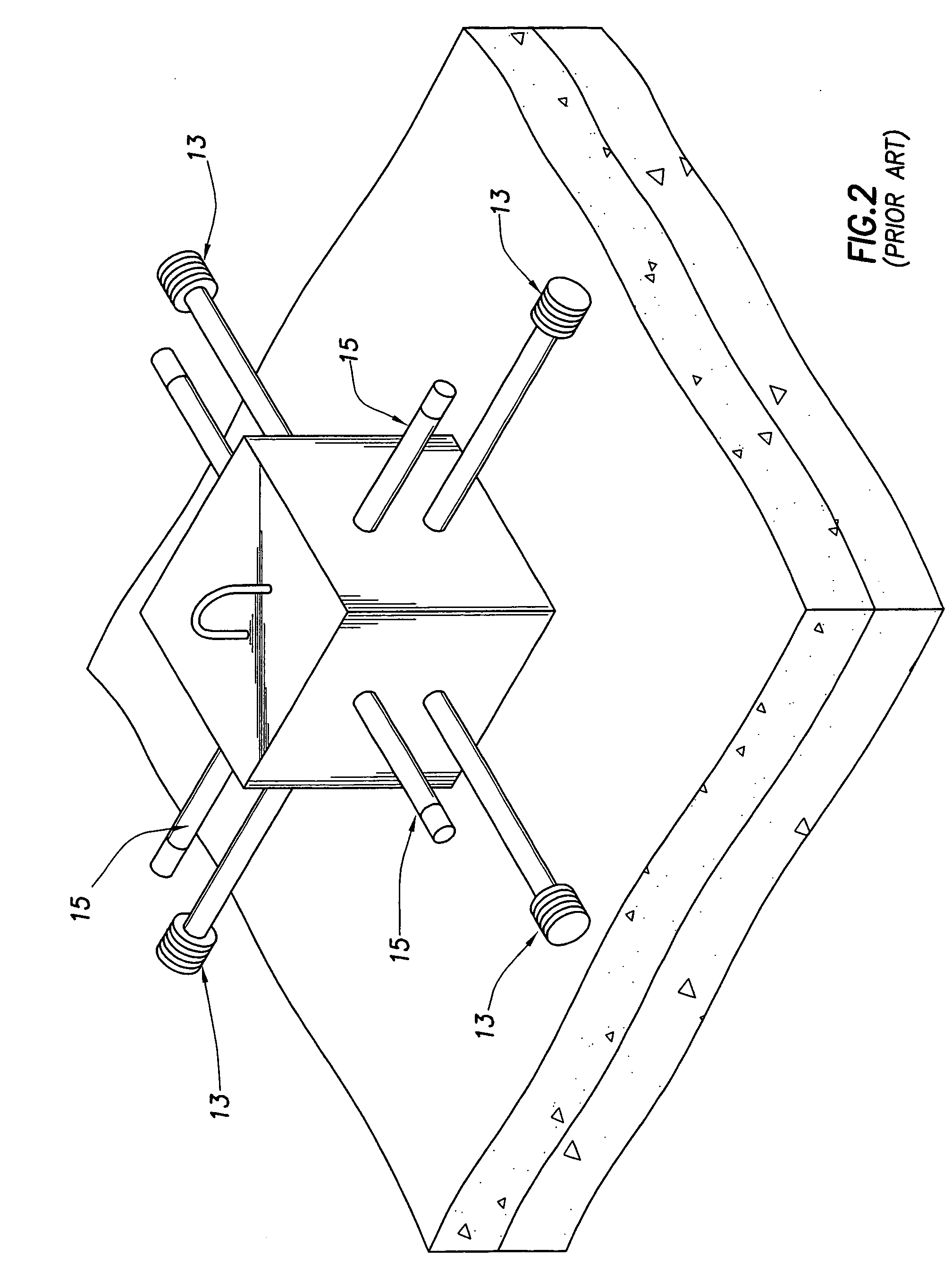
However, on land, it is not practical to measure the
electric field continuously (e.g., with a large number of densely-packed sampling points), nor is it practical to move the transmitting electrodes continuously as would be necessary if the subsurface were to be “illuminated” by all possible configurations of the injected currents.
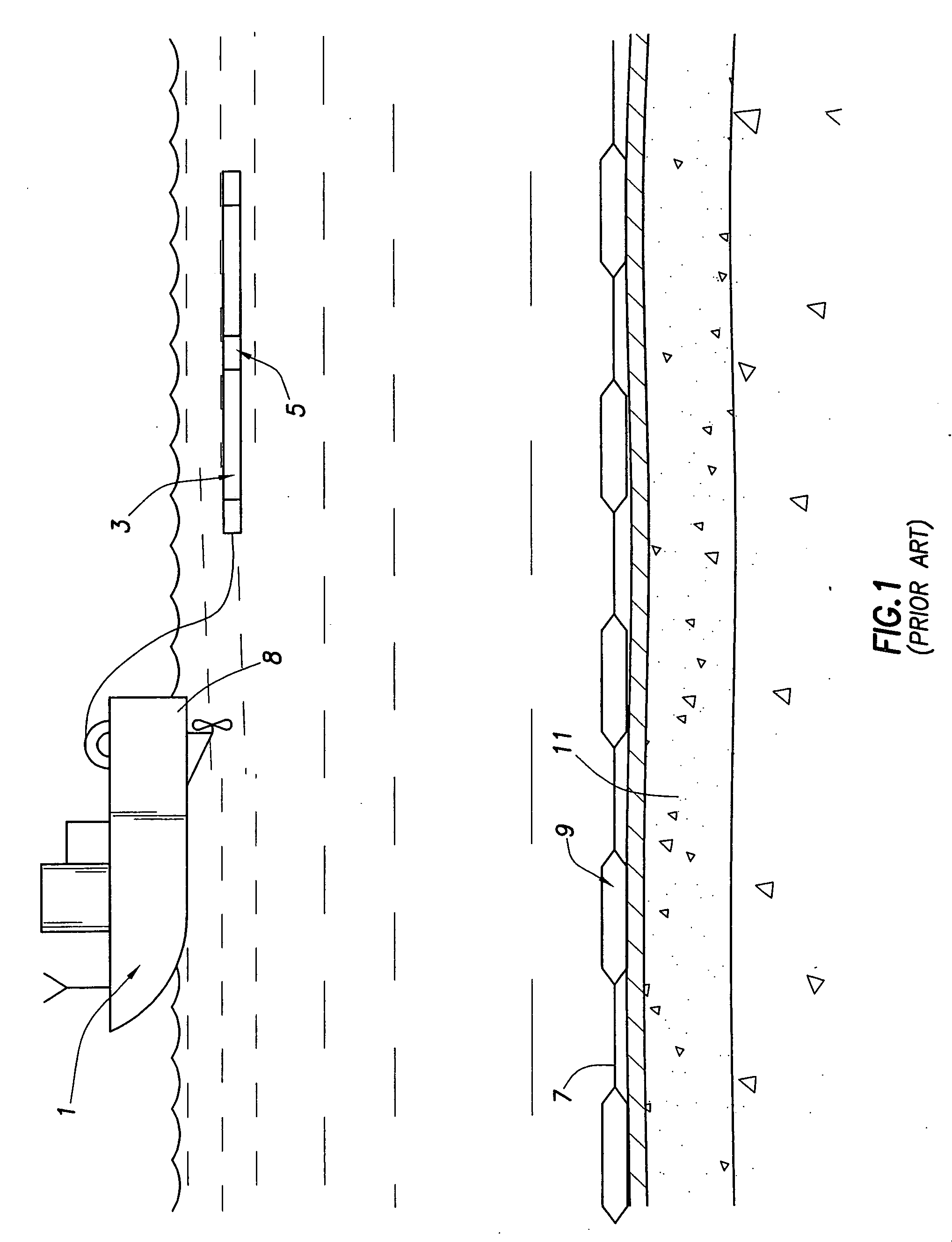
Because of the difficulties in obtaining data for continuous coverage surveys on land, prior art methods instead use discrete arrays in which current injection and
voltage measuring electrodes are regularly spaced, typically along a profile.

