Lithographic projection apparatus and device manufacturing method

a technology of lithographic projection and manufacturing method, which is applied in the direction of lighting and heating apparatus, printing, instruments, etc., can solve the problems of large radiation within the radiation beam cannot be modulated, and the patterned beam on the substrate requires a complex and expensive projection system

Active Publication Date: 2005-06-23
ASML NETHERLANDS BV
View PDF23 Cites 50 Cited by
  • Summary
  • Abstract
  • Description
  • Claims
  • Application Information

AI Technical Summary

Benefits of technology

[0012] In these embodiments, the projection optics used to project the beam onto the first array of focusing elements and the requirements of the projection system to project the patterned beam onto the second array of focusing elements can be the same as would be used if the array of individually controllable elements were to be uniformly exposed and projected onto the substrate. However, the first array of focusing elements can still focus a portion of the radiation beam onto each of the individually controllable elements, thereby allowing a greater proportion of the radiation beam to be modulated.

Problems solved by technology

Therefore a significant proportion of the radiation within the radiation beam cannot be modulated.
However, projecting such a projection beam of radiation onto the array of individually controllable elements and subsequently projecting the patterned beam onto the substrate requires a complex and consequently expensive projection system.

Method used


Image

  • Lithographic projection apparatus and device manufacturing method
  • Lithographic projection apparatus and device manufacturing method
  • Lithographic projection apparatus and device manufacturing method

Examples


Embodiment Construction

Overview and Terminology

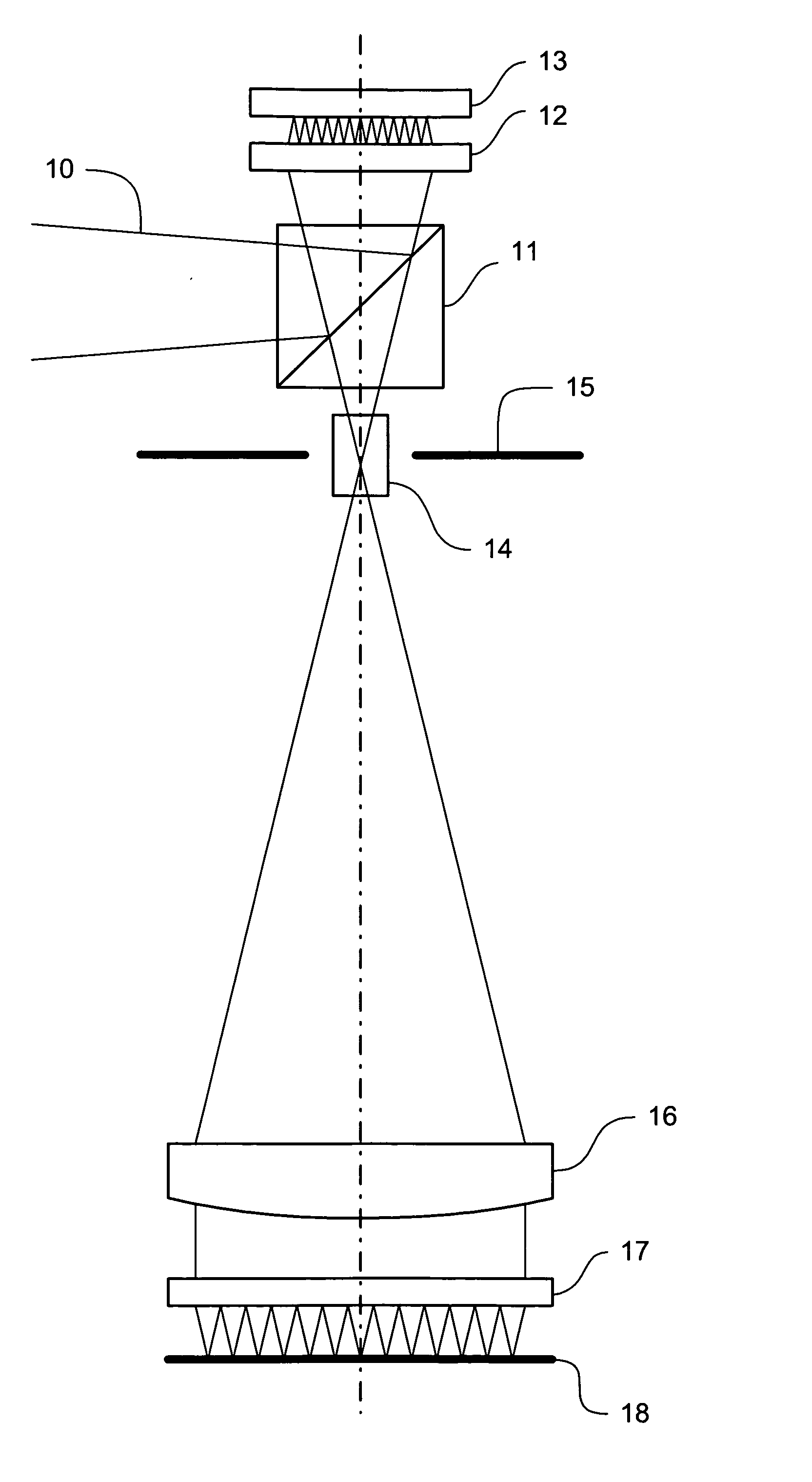
[0026] The term “array of individually controllable elements” as here employed should be broadly interpreted as referring to any device that can be used to endow an incoming radiation beam with a patterned cross-section, so that a desired pattern can be created in a target portion of the substrate; the terms “light valve” and “Spatial Light Modulator” (SLM) can also be used in this context. Examples of such patterning device include:

[0027] A programmable mirror array, which may comprise a matrix-addressable surface having a viscoelastic control layer and a reflective surface. The basic principle behind such an apparatus is that (for example) addressed areas of the reflective surface reflect incident light as diffracted light, whereas unaddressed areas reflect incident light as undiffracted light. Using an appropriate spatial filter, the said undiffracted light can be filtered out of the reflected beam, leaving only the diffracted light to reach the substra...


PUM

PropertyMeasurementUnit
wavelengthaaaaaaaaaa

Abstract

A system and method is used to pattern a substrate. A projection beam received from a radiation system is patterned using an array of individually controllable elements. A portion of the projection beam is directed directly onto one of the individually controllable elements and collecting radiation reflected therefrom using each one of a first array of focusing elements. An image of the first array of focusing elements is projected onto a second array of focusing elements using a projection system, such that radiation reflected from one of the individually controllable elements is projected via one of the focusing elements in the first array of focusing elements and the projection system to one of the focusing elements in the second array which focuses the radiation onto a spot on the substrate.

Description

BACKGROUND OF THE INVENTION [0001] 1. Field of the Invention [0002] The present invention relates to a lithographic projection apparatus. [0003] 2. Related Art [0004] Lithographic projection apparatus are used in the manufacture of integrated circuits (ICs), flat panel displays (FPDs), and other devices involving fine structures. An array of individually controllable elements generates a pattern corresponding to an individual layer of, for example, the IC, and this pattern is imaged onto a target portion (e.g., comprising part of one or several dies) on a substrate (e.g., a silicon wafer, glass plate, or the like) that has been coated with a layer of radiation-sensitive material (e.g., resist). [0005] Prior to this imaging step, the substrate may undergo various procedures, such as priming, resist coating, and a soft bake. After exposure, the substrate may be subjected to other procedures, such as a post-exposure bake (PEB), development, a hard bake, and measurement / inspection of th...

Claims


Application Information

Patent Timeline
Patent Type & Authority Applications(United States)
IPC IPC(8): G03F7/20H01L21/027
CPCG03F7/70275G03F7/70291G03F7/70933G03F7/70916G03F7/70866G03F7/20
Inventor DE JAGER, PIETER WILLEM HERMAN
Owner ASML NETHERLANDS BV
Why Eureka
Try Eureka