
Lane recognizing image processing system

a technology of image processing and lane recognition, which is applied in the direction of vehicular safety arrangements, pedestrian/occupant safety arrangements, instruments, etc., can solve the problems of increasing hardware and software load, difficult to realize lane recognition with reasonable accuracy, and poor visibility of botts' dots lane markings, etc., to achieve enhanced reliability and mitigate load on hardware and software.

Active Publication Date: 2005-06-23
MITSUBISHI ELECTRIC CORP
View PDF4 Cites 45 Cited by
  • Summary
  • Abstract
  • Description
  • Claims
  • Application Information

AI Technical Summary

Benefits of technology

The present invention provides a lane recognizing image processing system for vehicles that can reliably recognize lane markings even when traveling on roads with erroneous recognition. The system uses a method of setting an intermediate point in the lane marking as a candidate point and invalidating the result if the candidate point is on a single dot. This improves the reliability of the lane recognition and reduces the load on the system. The system includes an image pickup system, a lane marking candidate point extraction system, and a lane recognizing system installed on the vehicle. The lane marking candidate points are converted to lane marking candidate point positions to improve the accuracy of the lane recognition. Overall, the invention provides a reliable and efficient system for recognizing lane markings even in challenging driving conditions.

Problems solved by technology

In this conjunction, it is noted that when compared with the painted lane markings such as white lines and yellow lines, visibility of the Botts' dots lane markings is extremely poor because of low contrast between the Botts' dots lane markings and the road surface and because of discontinuity of the Botts' dots lane markings as viewed in the direction in which the motor vehicle is traveling, as a result of which not a little difficulty is encountered in the recognition of the lane by the image processing system.
Furthermore, in the case where the image recognition is performed by resorting to a same lane recognition algorithm as that for the ordinary lane marking recognition, there arises the necessity of discriminating the signals originating in the Botts' dots from noise for thereby separating the Botts' dot signal from the noise, which will incur increasing in the load imposed on hardware and software designed for post-processing of the lane images picked-up.
Consequently, the lane recognizing image processing system is constantly set to the state incapable of recognizing the lane markings on the Botts' dots-laid road, giving rise to a problem.
With the lane recognizing image processing system disclosed in JP-A-1991-158976, it is difficult to realize the lane recognition with reasonable accuracy for the group of straight lines composed of edge points of only one dot in the case where the dot is of a circular form whose contour line does not extend in parallel with the lane boundary line even if the Hough conversion of high noise insusceptibility is resorted to.
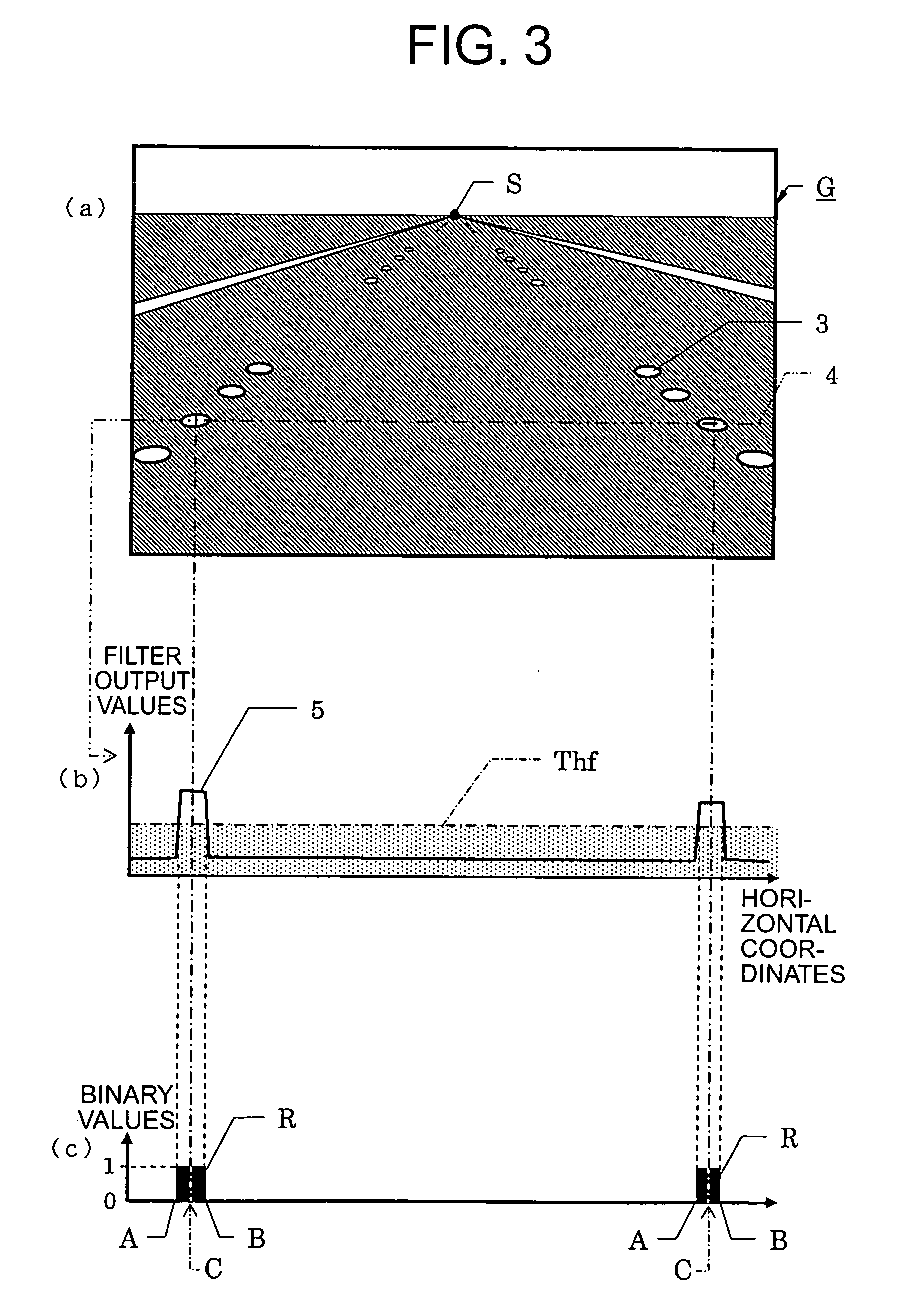
In this conjunction, it is however to be mentioned in conjunction with the decision as to existence of the lane marking candidate point(s) C only on the single dot 3 that the decision will result in that the recognition is impossible even in the case where approximation with a straight line interconnecting two Botts' dots 3 is possible when the decision is made on the basis of only the number of the candidate points, giving rise to a problem.
However, it will incur increasing of the cost involved in the arithmetic operation to check all possible combinations of the inter-point distances.
As the countermeasures to this end, there can be mentioned a method of invalidating the information derived from the lane marking candidate point C. This method is however disadvantageous in that the result of the lane recognition can not be referenced even when only one given frame becomes invalid in the course of traveling on the Botts' dots-laid road.
Further, when the lane marking search is performed with reference to the result of the lane recognition obtained precedingly, speedy restoration of the lane recognition will become difficult.
Besides, the invalidation method mentioned above suffers an additional problem that when the result of the preceding lane recognition is being delivered as the output data notwithstanding that the result of the preceding lane recognition is erroneous, the output data of the erroneous recognition can not be corrected until the result of the succeeding lane recognition not invalidated is made available.
However, when this decision is made on the basis of only the number of the lane marking candidate point(s) C, the decision may result in that the recognition is impossible even if approximation with a straight line interconnecting the two dot points 3 is possible, giving rise to a problem.
However, this solution will incur increasing of the cost involved in the arithmetic operation because all possible combinations of the inter-point distances have to be referenced.
Further, in the case where existence of the lane marking candidate only on the single dot 3 is made apparent, the information of low reliability derived from this lane marking candidate is invalidated.
This method is however disadvantageous in that the result of the lane recognition can not be referenced even in the case where only one given frame is rendered invalid in the course of traveling on the Botts' dots-laid road.
Further, when the lane marking search is performed with reference to the result of the lane recognition obtained precedingly, difficulty is encountered in the speedy restoration of the lane recognition.
Besides, the invalidation method mentioned above suffers an additional problem that when the result of the preceding lane recognition is being delivered as the output data notwithstanding that the result of the preceding lane recognition is erroneous, the output data of the erroneous recognition can not be corrected until the result of the succeeding valid lane recognition becomes available.

Method used


Image

  • Lane recognizing image processing system
  • Lane recognizing image processing system
  • Lane recognizing image processing system

Examples


embodiment 1

[0060] Now, the lane recognizing image processing system according to a first embodiment of the present invention will be described by reference to the drawings.

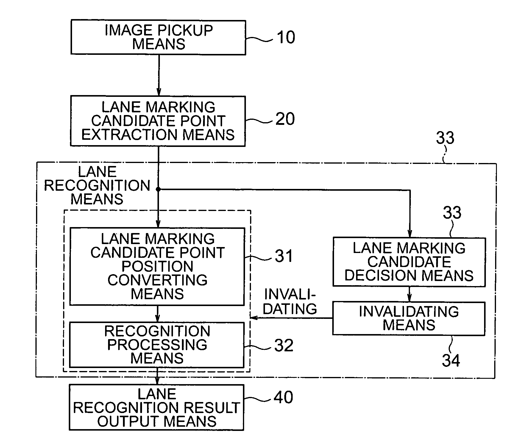
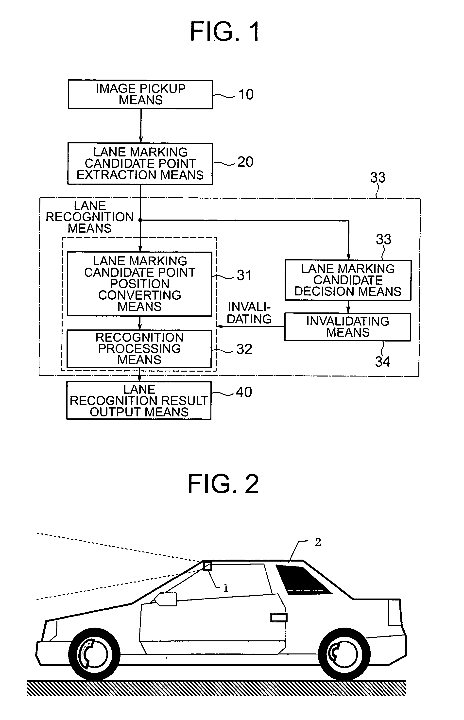
[0061]FIG. 1 is a block diagram showing a functional configuration of the lane recognizing image processing system according to the first embodiment of the invention, and FIG. 2 is a view showing an outer appearance of a motor vehicle which is equipped with the lane recognizing image processing system.

[0062] As can be seen in FIG. 2, a camera 1 constituting a major part of an image pickup means is mounted on a motor vehicle 2 at a front top portion thereof for taking pictures or images of scenes which make appearance in front of the motor vehicle 2 in the case of traveling thereof.

[0063] Referring to FIG. 1, the lane recognizing image processing system is comprised of an image pickup means 10 including the camera 1 mentioned above, a lane marking candidate point extraction means 20, a lane recognizing means 30 and a lane ...

embodiment 2

[0170] Next, description will be made of the lane recognizing image processing system according to a second embodiment of the present invention, which system differs from the first embodiment of the invention in the respect that the lane recognition means additionally includes a lane recognition result storing means for validating the precedingly stored information when the invalidation processing is executed.

[0171] Now referring to FIG. 12, description will be directed to the lane recognizing image processing system according to the second embodiment of the invention in which the lane recognition result storing means 36 is incorporated.

[0172]FIG. 12 is a functional block diagram showing a configuration of the lane recognizing image processing system according to the second embodiment of the invention. In FIG. 12, components or means same as or equivalent to those described hereinbefore by reference to FIG. 1 are denoted by like reference numerals affixed with or without “A”.

[017...

embodiment 3

[0189] In the case of the lane recognizing image processing system according to the second embodiment of the present invention described above, the result of the preceding lane recognition is delivered when the invalidation processing is executed. A third embodiment of the present invention concerns the lane recognizing image processing system which is arranged such that the lane recognizing means includes a time-based average processing means, wherein when only one given frame becomes invalid for the lane recognition in the course of the lane recognition processing, a result of time-based average processing for which adverse influence of the lane recognition invalidation is mitigated is delivered as the output of the time-based average processing means.

[0190] In the following, the lane recognizing image processing system according to the third embodiment of the invention which system incorporates the time-based average processing means 37 will be described by reference to FIG. 13....


PUM


Abstract

A lane recognizing image processing system for recognizing lane markings laid on a driving road for motor vehicles includes a lane marking candidate point extraction means (20) for extracting lane marking candidate points (C) from an image (G) taken by an image pickup means (10) mounted on the motor vehicle, and a lane recognizing means (30) for recognizing a lane defined on the road on the basis of set of the lane marking candidate points (C). The lane recognizing means (30) includes a lane marking candidate point position converting means (31) for recognizing as lane marking candidate point positions the positions of the lane marking candidate points (C) transformed onto a straight line extending toward a null point.

Description

BACKGROUND OF THE INVENTION [0001] 1. Field of the Invention [0002] The present invention generally relates to a lane recognizing image processing system for generating vehicle position information used in a motor vehicle control system such as typified by a lane keep system (LKS) or the like, which system is designed for ensuring precautionary safety for the operation of a motor vehicle by activating a lane departure warning system (LDWS) to thereby mitigate a burden otherwise imposed on the operator or driver of the motor vehicle. [0003] 2. Description of Related Art [0004] In general, the object to be recognized by the lane recognizing image processing system is lane markings representing lane boundary lines which are applied or painted on a road in white or yellow. Of course, various forms of the lane markings are adopted in dependence on countries and / or localities. By way of example, in California in United States of America, there exist freeways and prefectural or state roads...

Claims


Application Information

Patent Timeline
Patent Type & Authority Applications(United States)
IPC IPC(8): B60R1/00B60R21/00G06T1/00G06V30/144G06T7/00G06T7/60G06V10/44G08G1/16H04N7/18
CPCG06K9/00798G06T7/0042G06K9/4604G06T7/73G06V20/588G06V10/44
Inventor YAMAMOTO, TAKAYUKIFUJII, YOSHIYUKIISHIKURA, HISASHIFUJIE, KENICHI
Owner MITSUBISHI ELECTRIC CORP
Learn More