Heart valve anchor and method

a heart valve and anchoring technology, applied in the field of heart valve anchoring and methods, can solve the problems of heart valve replacement surgery, adverse reactions to anesthesia medications, bleeding, stroke, etc., and achieve the effect of convenient deployment and expansion of the apparatus

Inactive Publication Date: 2005-06-23
BOSTON SCI SCIMED INC
View PDF99 Cites 688 Cited by
  • Summary
  • Abstract
  • Description
  • Claims
  • Application Information

AI Technical Summary

Benefits of technology

[0017] The invention also includes a delivery system that facilitates deployment and expansion of the apparatus to endovascularly replace the heart valve and, in some embodiments, retrieve the apparatus.

Problems solved by technology

Valve replacement surgery is a highly invasive operation with significant concomitant risk.
Risks include bleeding, infection, stroke, heart attack, arrhythmia, renal failure, adverse reactions to the anesthesia medications, as well as sudden death.
PVT's device suffers from several drawbacks.
Deployment of PVT's stent is not reversible, and the stent is not retrievable.
This is a critical drawback because improper positioning too far up towards the aorta risks blocking the coronary ostia of the patient.
Furthermore, a misplaced stent / valve in the other direction (away from the aorta, closer to the ventricle) will impinge on the mitral apparatus and eventually wear through the leaflet as the leaflet continuously rubs against the edge of the stent / valve.
Another drawback of the PVT device is its relatively large cross-sectional delivery profile.
The PVT system's stent / valve combination is mounted onto a delivery balloon, making retrograde delivery through the aorta challenging.
An antegrade transseptal approach may therefore be needed, requiring puncture of the septum and routing through the mitral valve, which significantly increases complexity and risk of the procedure.
Very few cardiologists are currently trained in performing a transseptal puncture, which is a challenging procedure by itself.
Standard self-expanding systems have very poor accuracy in deployment, however.
It is therefore often impossible to know where the ends of the stent will be with respect to the native valve, the coronary ostia and the mitral valve.
Visualization prior to final and irreversible deployment cannot be done with standard self-expanding systems, however, and the replacement valve is often not fully functional before final deployment.
Another drawback of prior art self-expanding replacement heart valve systems is their lack of radial strength.
However when the stent has a valve fastened inside it, as is the case in aortic valve replacement, the anchoring of the stent to vessel walls is significantly challenged during diastole.
Moreover, a self-expanding stent without sufficient radial force will end up dilating and contracting with each heartbeat, thereby distorting the valve, affecting its function and possibly migrating and dislodging completely.
Simply increasing strut thickness of the self-expanding stent is not a practical solution as it runs the risk of larger profile and / or plastic deformation of the self-expanding stent.
While providing for an aortic approach, devices described in the Garrison patent application suffer from several drawbacks.
First, the stent portion of the device is delivered across the native valve as a single piece in a single step, which precludes dynamic repositioning of the stent during delivery.
Stent foreshortening or migration during expansion may lead to improper alignment.
This increases an immediate risk of blocking the coronary ostia, as well as a longer-term risk of migration of the device post-implantation.
Tissue may protrude through these gaps, thereby increasing a risk of improper seating of the valve within the stent.

Method used


Image

  • Heart valve anchor and method
  • Heart valve anchor and method
  • Heart valve anchor and method

Examples


Embodiment Construction

[0069] While preferred embodiments of the present invention have been shown and described herein, it will be obvious to those skilled in the art that such embodiments are provided by way of example only. Numerous variations, changes, and substitutions will now occur to those skilled in the art without departing from the invention. It should be understood that various alternatives to the embodiments of the invention described herein may be employed in practicing the invention. It is intended that the following claims define the scope of the invention and that methods and structures within the scope of these claims and their equivalents be covered thereby.

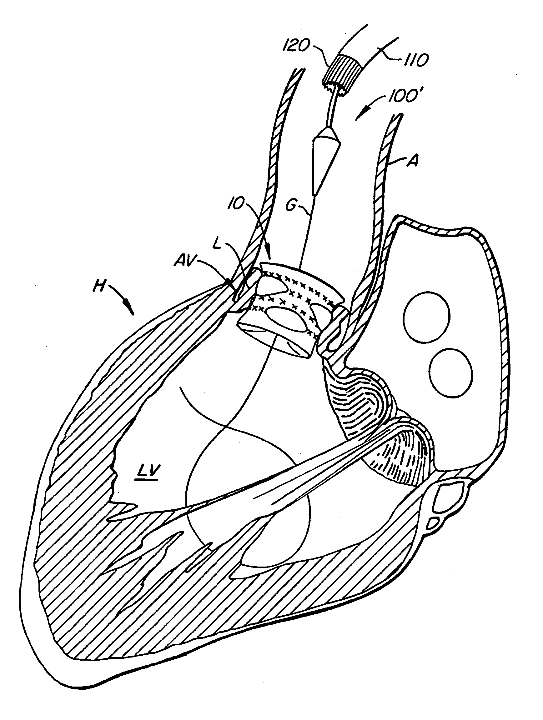
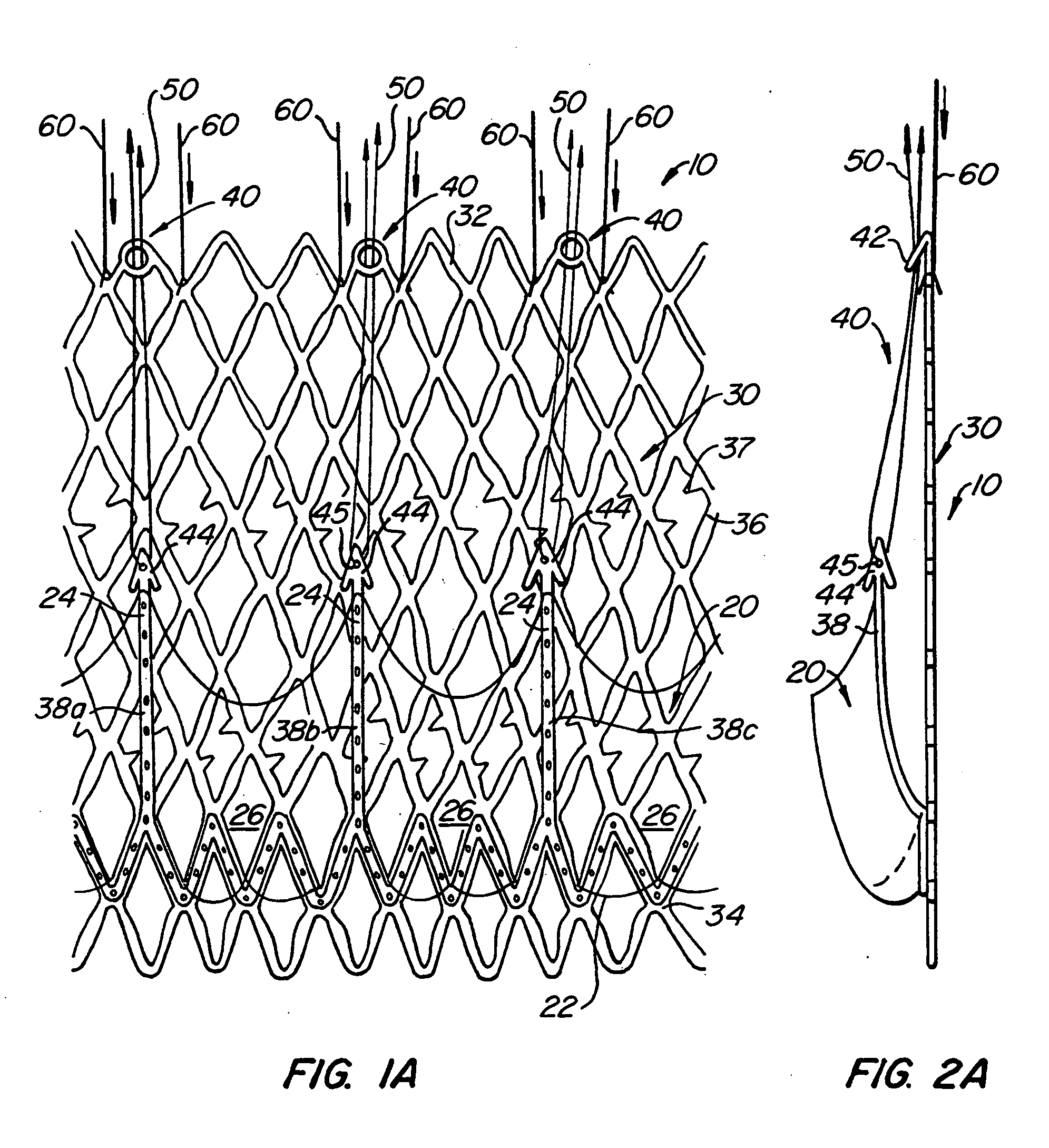
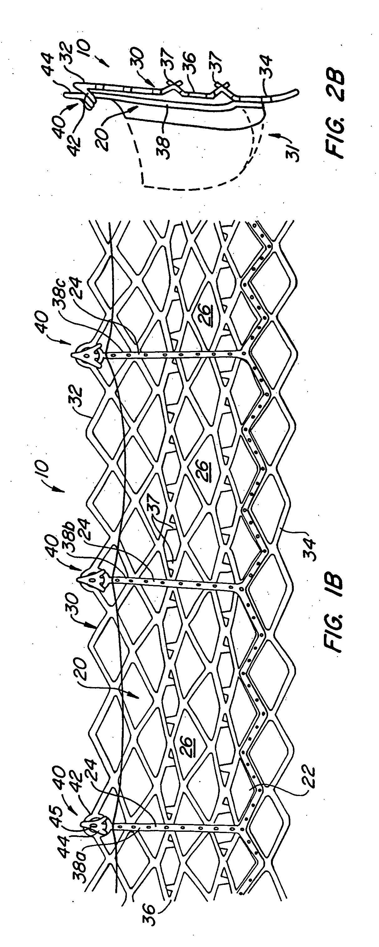
[0070] With reference now to FIGS. 1-4, a first embodiment of replacement heart valve apparatus in accordance with the present invention is described, including a method of actively foreshortening and expanding the apparatus from a delivery configuration and to a deployed configuration. Apparatus 10 comprises replacement valve 20 di...


PUM


Abstract

Apparatus for endovascularly replacing a patient's heart valve. In some embodiments the apparatus includes an expandable anchor with a lip region and a skirt region; and a replacement valve, wherein the lip region and skirt region are configured for percutaneous expansion to engage leaflets of the heart valve. The invention is also a method for endovascularly replacing a patient's heart valve. In some embodiments the method includes the steps of endovascularly delivering apparatus including an anchor having lip and skirt regions, and a replacement valve coupled to the anchor, to a vicinity of the heart valve in a collapsed delivery configuration; and expanding the apparatus such that leaflets of the heart valve are captured between the lip and skirt regions of the anchor.

Description

BACKGROUND OF THE INVENTION [0001] The present invention relates to methods and apparatus for endovascularly replacing a heart valve. More particularly, the present invention relates to methods and apparatus for endovascularly replacing a heart valve with a replacement valve using an expandable and retrievable anchor. [0002] Heart valve surgery is used to repair or replace diseased heart valves. Valve surgery is an open-heart procedure conducted under general anesthesia. An incision is made through the patient's sternum (sternotomy), and the patient's heart is stopped while blood flow is rerouted through a heart-lung bypass machine. [0003] Valve replacement may be indicated when there is a narrowing of the native heart valve, commonly referred to as stenosis, or when the native valve leaks or regurgitates. When replacing the valve, the native valve is excised and replaced with either a biologic or a mechanical valve. Mechanical valves require lifelong anticoagulant medication to pre...

Claims


Application Information

Patent Timeline
Patent Type & Authority Applications(United States)
IPC IPC(8): A61F2/06A61F2/24A61F2/90
CPCA61F2/2418A61F2/2433A61F2/2436A61F2/2439A61F2230/0078A61F2250/006A61F2220/0016A61F2230/005A61F2230/0054A61F2002/9528A61F2/90A61F2220/005A61F2220/0058A61F2230/008A61F2/2409A61F2/2412A61F2/243
Inventor SALAHIEH, AMRBRANDT, BRIAN D.MOREJOHN, DWIGHT P.HAUG, ULRICH R.DUERI, JEAN-PIERREVALENCIA, HANS F.GESHLIDER, ROBERT A.KROLIK, JEFF
Owner BOSTON SCI SCIMED INC
Why Eureka
Try Eureka