Memory updating system for field device

a field device and memory update technology, applied in the field of memory updating system for field devices, can solve the problems of increasing the current consumption inside the field device temporarily, increasing the power consumption for data writing, and increasing the possibility of firmware bugs, so as to reduce the power consumption during firmware updates and shorten the updating tim

Active Publication Date: 2005-06-23
YOKOGAWA ELECTRIC CORP
View PDF8 Cites 17 Cited by
  • Summary
  • Abstract
  • Description
  • Claims
  • Application Information

AI Technical Summary

Benefits of technology

[0018] The object of the present invention is to provide a memory updating system for a field device for which an increase in the consumption of power during a firmware update can be minimized, and the updating time can also be shortened. In the description, a host system is responsible for the updating of the firmware for a field device. However, this invention can also be applied for the updating of firmware by using a “temporary device” that conforms to the fieldbus standards, i.e., a setup tool that is temporarily connected for the maintenance or the parameter setup of the field device. This temporary device is also included as a host system described in the description.

Problems solved by technology

Furthermore, since there is the variety of functions, the possibility that bugs will exist in the firmware is also increased.
However, the field device used to update the firmware has the following problems.
However, current consumption inside of the field device temporarily increases during the update of the nonvolatile memory.
Further, the increase in the power consumption for data writing was the maximum of 20 mA, while the actual measurement was 1 mA.
Consequently, the costs will be increased.
However, because of a limitation in the transfer rate (31.25 kbps) for the fieldbus 8, about thirty minutes, for example, is required to update each device.
When ten field devices 9 are constituted in one segment, a maximum of 300 minutes is taken in order to update all of the field devices 9, so that this is not practical.
Thus, since the power supplied to the field device 9 would become insufficient, data could not be rewritten, and the number of field devices 9 that could be connected to the fieldbus 8 is limited.

Method used


Image

  • Memory updating system for field device
  • Memory updating system for field device
  • Memory updating system for field device

Examples


Embodiment Construction

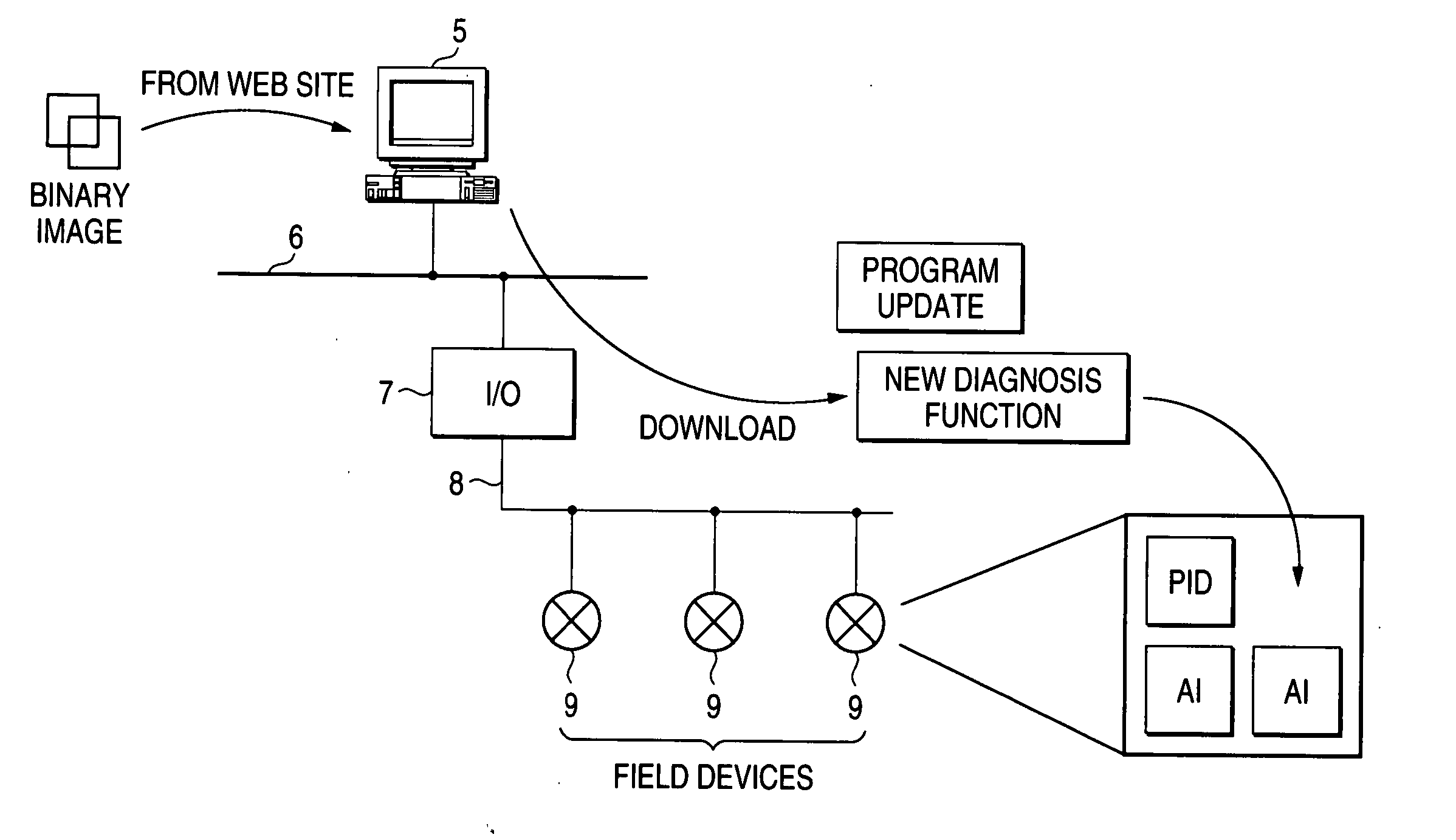
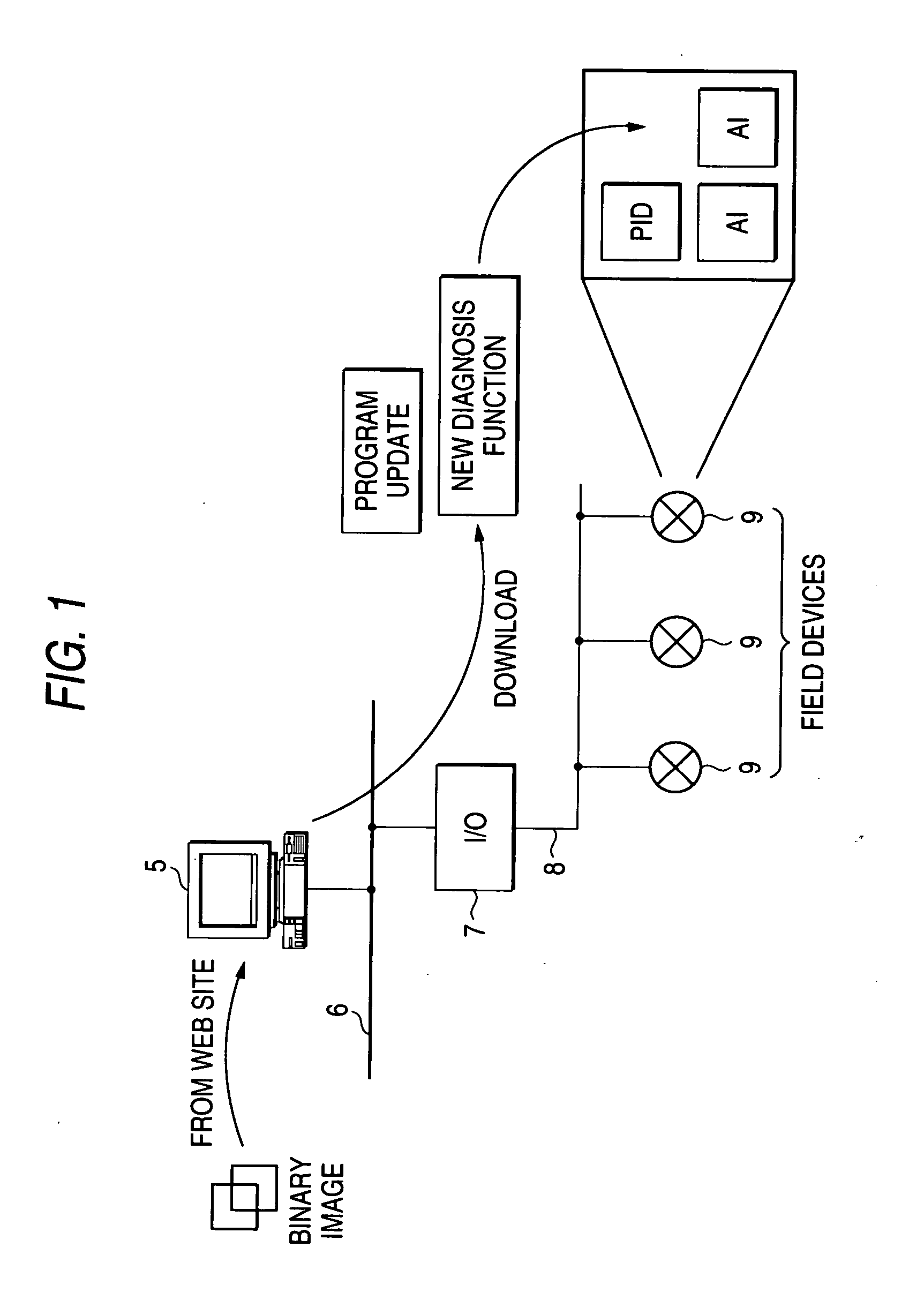
[0026] A embodiment of the present invention will now be described in detail with reference to the drawings. Since the principal configuration of a process control system of the embodiment is the same as that in FIG. 1, no further explanation will be given. The field devices 9 are separated into segments, and managed in accordance with the configuration of the process control system, and a plurality of the field devices 9 are included in one segment. These segments are employed as units to update the contents of the nonvolatile memories of the field devices 9.

[0027]FIG. 4 is a diagram showing one field device 9 according to the embodiment of the present invention. FIG. 5 is a diagram showing the configuration of an MAU (Media Attachment Unit) used for the embodiment.

[0028] In FIGS. 4 and 5, an MAU 11 is connected to a fieldbus (not shown in FIGS. 4 and 5), and functions as a D / A converter and an A / D converter, a transmission / reception circuit, and a circuit for generating the inte...


PUM


Abstract

A memory updating system for a field device involves a fieldbus, one or more field devices that incorporate a nonvolatile memory and are connected to the fieldbus, a host system that is directly or indirectly connected to the fieldbus and transmits an updating instruction and updating data to one of the field devices in order to update the nonvolatile memory of the field device, and a current control circuit that controls a current provided from the fieldbus. The current control circuit increases the current provided from the fieldbus to a value greater than a normal value before the field device erases data stored in the nonvolatile memory, and returns the current provided from the fieldbus to the normal value after the field device completes the erasing of the data stored in the nonvolatile memory.

Description

BACKGROUND OF THE INVENTION [0001] 1.Field of the Invention The present invention relates to a memory updating system for a field device, used at a process field, that rewrites data, such as firmware or configuration data, stored in a nonvolatile memory in the field device. [0002] 2.Description of the Related Art JP-A-2001-350504 and JP-A-2003-510710 are referred to as related art of the memory updating system. [0003] JP-A-2001-350504 discloses the steps of: performing a calculation process in a first memory area; deactivating the first memory area; and activating a second memory area, whereby reconfiguration can be performed in an online mode. [0004] JP-A-2003-510710 discloses the steps of: employing a standard communication protocol to download a program instruction from a host to a field device; and storing the program instruction, whereby re-programming of a field device in a process control network is performed. [0005]FIG. 1 is a diagram showing the general configuration of a p...

Claims


Application Information

Patent Timeline
Patent Type & Authority Applications(United States)
IPC IPC(8): G01D5/00G05B11/01G05B15/00G06F12/00G05B19/042G05B19/18G06F9/445G06F13/16
CPCG01D5/00G05B2219/25428G05B2219/23314G05B19/0426
Inventor SAITO, YOJITAKAHASHI, SEIICHIROOCHIAI, SATORUNIKKUNI, MASAAKI
Owner YOKOGAWA ELECTRIC CORP
Why Eureka
Try Eureka