In-plane switching mode liquid crystal display device

Inactive Publication Date: 2005-06-30
LG DISPLAY CO LTD
View PDF21 Cites 79 Cited by
  • Summary
  • Abstract
  • Description
  • Claims
  • Application Information

AI Technical Summary

Problems solved by technology

The liquid crystal material injected between the first and second substrates may deteriorate when a DC voltage is applied for a long time.
However, the frame inversion method is sensitive to flicker generated according to an asymmetrical transmittance between the positive and negative polarities.
In addition, the frame inversion method is susceptible to crosstalk caused by interference between data signals of adjacent pixels.
However, the polarity of the data voltage is the same along a horizontal direction, so that horizontal crosstalk is generated, and consumption current is increased due to an increase of the number of switching operations, as compared with that during the frame inversion.
However, the dot inversion method is problematic since the dot inversion method has a high co

Method used


Image

  • In-plane switching mode liquid crystal display device
  • In-plane switching mode liquid crystal display device
  • In-plane switching mode liquid crystal display device

Examples


Embodiment Construction

[0061] Reference will now be made in detail to the embodiments of the present invention, examples of which are illustrated in the accompanying drawings. Wherever possible, the same reference numbers will be used throughout the drawings to refer to the same or like parts.

[0062] Hereinafter, an IPS mode LCD device according to one embodiment of the present invention will be described with reference to the accompanying drawings.

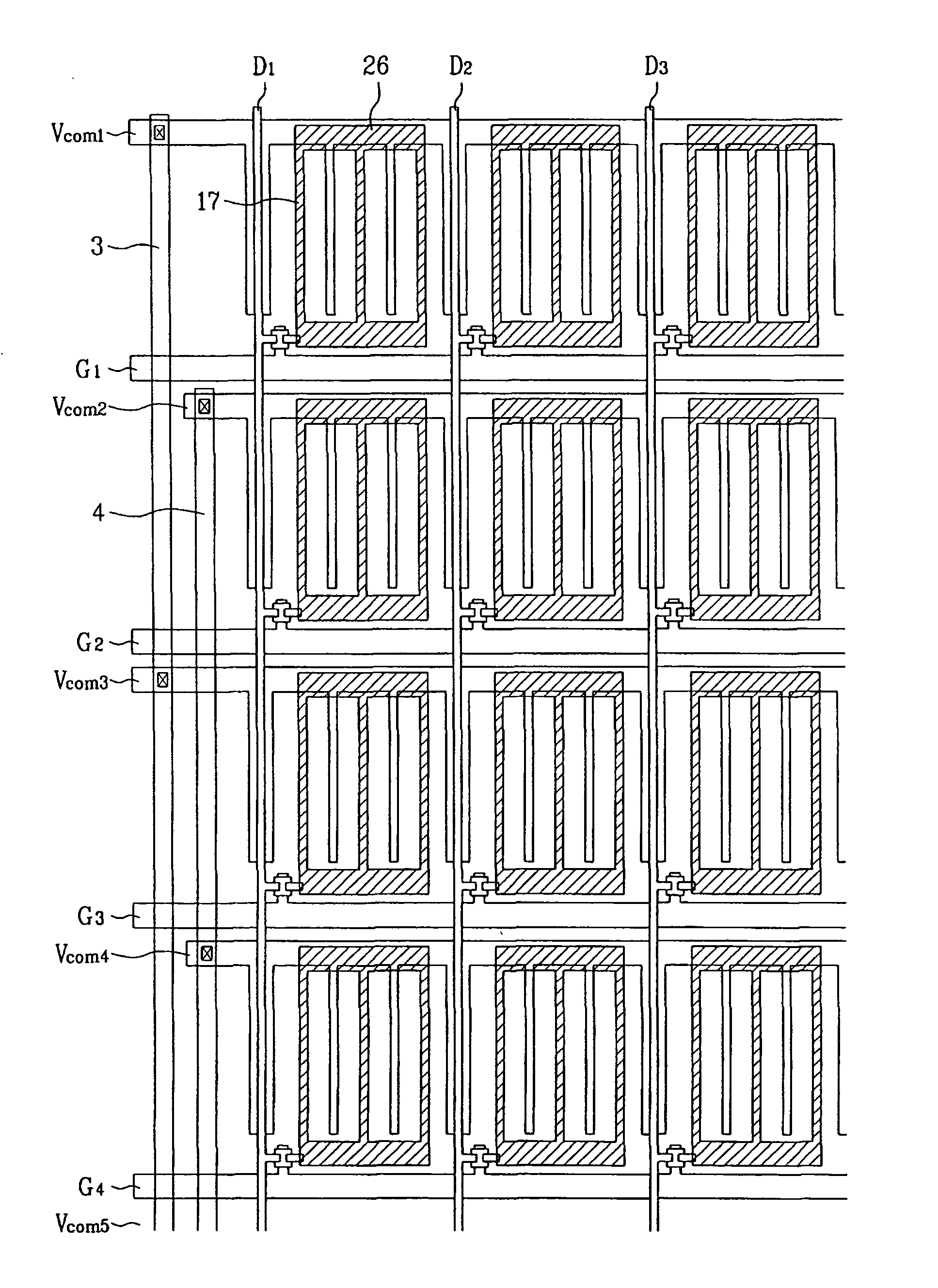
[0063]FIG. 8 is an equivalent circuit view of an IPS mode LCD device according to the preferred embodiment of the present invention. The IPS mode LCD device according to the preferred embodiment of the present invention includes a plurality of gate lines (G1, G2, G3, G4, . . . ) and a plurality of data lines (D1, D2, D3, D4, . . . ), a plurality of common lines (Vcom1, Vcom2, Vcom3, . . . ), a plurality of thin film transistors, a pixel electrode (‘17’ of FIG. 2), and a storage capacitor Cst and a liquid crystal capacitor CLC. At this time, the plurality of ga...


PUM


Abstract

An IPS mode LCD device is disclosed in which a common voltage drop and delay is decreased. The LCD includes gate and data lines crossing each other to define pixel regions. Thin film transistors are formed at crossing portions of the gate and data lines. Common lines are parallel with the gate lines and common electrodes project from the common lines parallel with the data lines. Pixel electrodes connected with drain electrodes of the thin film transistors are formed in the pixel regions between the parallel common electrodes. A first common voltage supplying line applies a first common voltage or a second common voltage to a closed circuit formed by grouping the adjacent odd numbered common lines. A second common voltage supplying line applies the second common voltage or the first common voltage to a closed circuit formed by grouping the adjacent even numbered common lines.

Description

[0001] The present invention claims the benefit of the Korean Application No. P2003-100857, filed on Dec. 30, 2003, which is hereby incorporated by reference. BACKGROUND [0002] 1. Field of the Invention [0003] The present invention relates to an In-Plane Switching (IPS) mode liquid crystal display (LCD) device, and more particularly, to an IPS mode LCD device to decrease a common voltage drop and delay. [0004] 2. Discussion of the Related Art [0005] A liquid crystal display (LCD) device is a flat display. The LCD device changes optical anisotropy by applying an electric field to a liquid crystal layer. The LCD device has been widely used as it has a number of advantageous characteristics as compared with a conventional display using a cathode ray tube (CRT). These characteristics include low power consumption, thin profile, high resolution, and suitableness for a large size. [0006] The LCD device includes an LCD panel for displaying images, and a driving circuit part for supplying d...

Claims


Application Information

Patent Timeline
IPC IPC(8): G02F1/133G02F1/1343G02F1/136G09G3/36H01L21/00H01L29/04H01L29/15H01L29/786
CPCG02F1/134363G02F1/13439G09G2300/0434G09G3/3655G09G3/3614G02F1/1343
Inventor LEE, JAE KYUNLEE, DONG HOON
Owner LG DISPLAY CO LTD
Why Eureka
Try Eureka