Brushless motor

a brushless, motor technology, applied in the direction of sliding contact bearings, instruments, record information storage, etc., can solve the problems of low vibration, increase the cost of permanent magnets, and the method is not usually used in actual products, so as to achieve the effect of further enhancing the attraction for

Active Publication Date: 2005-06-30
MINEBEA MOTOR MFG
View PDF8 Cites 23 Cited by
  • Summary
  • Abstract
  • Description
  • Claims
  • Application Information

AI Technical Summary

Benefits of technology

[0010] The present invention has an object to provide a low-cost brushless motor that has a small vibration in the thrust direction, and a sufficient thrust attracting force obtained with a small and inexpensive magnet.
[0014] By providing a space between the outer periphery of the permanent magnet and the bottom receiving part as mentioned above, a leakage magnetic flux is reduced and a large attracting force is obtained even with a small magnet.
[0016] By forming the permanent magnet by being cut out from a block of anisotropic permanent magnet as mentioned above, productivity of the magnet is enhanced, and the cost of the magnet is reduced.
[0020] By fixing the pull-out-preventive stopper made of a magnetic material near the tip end portion of the shaft facing the permanent magnet, the attracting force is further enhanced.

Problems solved by technology

Rewritable DVD, for example, often performs writing at a maximum speed of about 6000 r / min, and since slight vibration of the disc may lead to a writing error, low vibration is. especially required for the spindle motor driving the disc.
However, such method is not usually used in actual products.
However, in order to secure a sufficient attracting force, a large permanent magnet needs be used, which increases the cost for the permanent magnet.
In the latter method of attracting a shaft with a permanent magnet, the attracting surface area is small and thus a sufficient attracting force is not obtained in many cases, resulting in that this method is seldom used.

Method used


Image

  • Brushless motor
  • Brushless motor
  • Brushless motor

Examples


first embodiment

(First Embodiment)

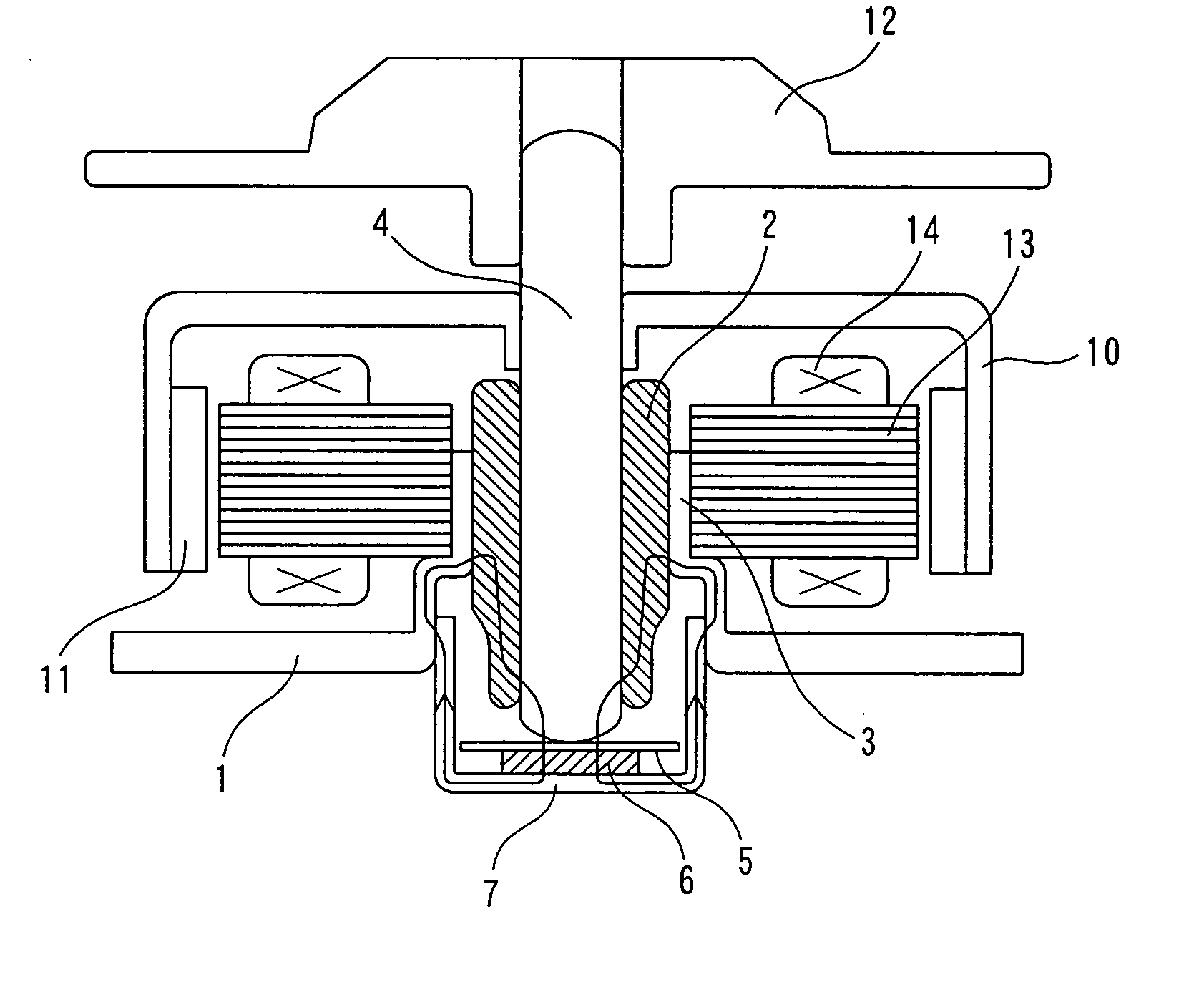
[0030]FIG. 1 is a schematic cross sectional view of a brushless motor according to a first embodiment of the present invention.

[0031] In FIG. 1, reference number 1 denotes a base for attaching a motor to an apparatus, which base 1 is formed by molding a coated steel plate by press working, and the cylindrical bearing boss 3 for fixing the bearing 2 at a central part is integrally formed therewith.

[0032] The bearing 2 is a sintering oil-containing bearing made of iron or alloy material of for example, iron and copper, has a cylindrical shape and is press fit and fixed to the inner periphery of the bearing boss 3.

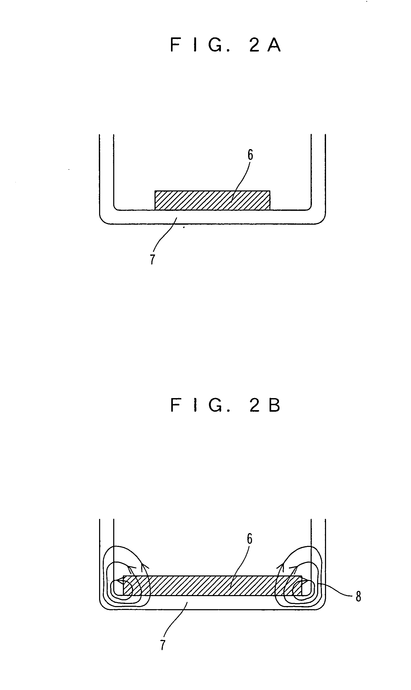
[0033] The shaft 4 is rotatably held by the bearing 2. A lower side end face of the shaft 4 has a tip end thereof formed into an R-shape, and is in a state to rotate with the thrust plate 5 (thrust receiving member) at a substantially point contacting state. The permanent magnet 6 formed into a triangular pole, a cube, a rectangular parallelepiped, a poly...

second embodiment

(Second Embodiment)

[0058]FIG. 6 is a schematic cross sectional view of a brushless motor according to a second embodiment of the present invention.

[0059] In FIG. 6, the configuration of the motor is substantially the same as the configuration of the motor according to the first embodiment shown in FIG. 1, but different in that a ring shaped pull-out-preventive stopper 9 made of iron is press fit and fixed at a portion of the tip end of the shaft 4 facing the permanent magnet 6.

[0060] By attaching a magnetic body near the tip end of the shaft 4 as above, a similar behavior as when the opposing surface areas of the shaft and the permanent magnet are made large is obtained, and the attracting force is improved.

[0061] When such magnetic body also acts as pull-out-preventive stopper for the rotor, there is no need to additionally provide a pull-out-preventive stopper and thus the cost of the motor is reduced.

[0062] The pull-out-preventive stopper 9 may not necessarily be made of iron...


PUM

PropertyMeasurementUnit
weight ratioaaaaaaaaaa
sizeaaaaaaaaaa
magnetic fluxaaaaaaaaaa

Abstract

The present invention provides a low vibration brushless motor for reducing the vibration of the motor in an axial direction. In the brushless motor, a bearing is provided in a bearing boss, a shaft is held by the bearing, an end face of the shaft is contacting a thrust receiving member, and the shaft is rotatably axially supported by the bearing. The brushless motor includes a permanent magnet for attracting the end face of the shaft in the thrust direction with the thrust receiving member therebetween, and a bottom receiving part for supporting the permanent magnet, wherein the bearing boss, bearing, shaft, and bottom receiving part are made of a magnetic material, and a closed magnetic path is formed so that a magnetic flux passes through the permanent magnet, bottom receiving part, bearing boss, bearing, and shaft.

Description

BACKGROUND OF THE INVENTION [0001] 1. Field of the Invention [0002] The present invention relates to a spindle motor and the like used in a magnetic disc and an optical disc. [0003] 2. Description of the Related Art [0004] Magnetic discs and the optical discs are becoming higher in speed and capacity year after year. Thus, high speed, high torque as well as low vibration and low noise are required for a spindle motor for driving the disc. [0005] Rewritable DVD, for example, often performs writing at a maximum speed of about 6000 r / min, and since slight vibration of the disc may lead to a writing error, low vibration is. especially required for the spindle motor driving the disc. [0006] A method of reducing vibration of a spindle motor (particularly reducing vibration in a direction of thrust) includes a method of reducing vibration by providing a permanent magnet on either a rotor side or a stator side to attract a rotor in the direction of thrust with the permanent magnet, and supp...

Claims


Application Information

Patent Timeline
Patent Type & Authority Applications(United States)
IPC IPC(8): H02K5/167F16C17/08F16C39/06G11B19/20H02K7/08H02K7/09
CPCF16C17/08F16C39/063F16C2370/12H02K7/085H02K7/09G11B19/2009
Inventor FUJINAKA, HIROYASUMASUDA, KUMIO
Owner MINEBEA MOTOR MFG
Why Eureka
Try Eureka