Spindle motor

a spindle motor and spindle body technology, applied in the direction of magnetic circuit rotating parts, instruments, magnetic circuit shape/form/construction, etc., can solve the problems of greater or smaller deviations, damage to components during pressfitting process, and inability to achieve the required holding force, so as to increase the effective length of the joint or the effective connecting surface, improve the effect of radial and axial runout of the rotor, and improve the effect of angularity

Inactive Publication Date: 2005-06-30
MINEBEAMITSUMI INC
View PDF5 Cites 4 Cited by
  • Summary
  • Abstract
  • Description
  • Claims
  • Application Information

AI Technical Summary

Benefits of technology

[0010] The advantage of the invention is that it increases the effective length of the joint or the effective connecting surface between the shaft shoulder on the rotor and the (hollow) shaft, the joint length of the overlapping area of connection preferably being at least half as long as the overall length of the hollow shaft. Increasing the guiding ratio (l / d) makes it possible to achieve excellent right angularity and firm seating of the shaft shoulder in the hollow shaft. This arrangement goes to decrease both the radial as well as the axial runout of the rotor and to reduce its tilt with respect to the rotational axis of the shaft. Over and above this, the shock resistance of the motor is also improved.
[0011] If it has been decided to use an interference fit between the shaft shoulder on the rotor and the hollow shaft, the interference of the shaft shoulder with respect to the inside diameter of the hollow shaft can be smaller in total due to the long length of the joint, so that the rotor can be connected to the shaft in a manner that is sparing of the components.
[0012] The connection can, however, also be made by bonding in which the fitting together of shaft shoulder and hollow shaft can also bring its advantages.
[0013] To achieve high precision, and above all reproducible precision, the shaft shoulder is preferably formed as an integral part of the rotor.
[0014] The invention can preferably be applied in spindle motors having a hydrodynamic bearing system. In an advantageous embodiment of the invention, the thrust plate—as part of the thrust bearing in the bearing system—is an integral part of the hollow shaft and is formed onto the lower end of the hollow shaft. This means that the bearing surfaces of the shaft and the thrust plate perpendicular to each other are formed with high precision as a single integral piece.
[0015] In another embodiment, the thrust plate is formed as an integral part of a plug that is inserted into the lower, open end of the hollow shaft and firmly fixed to the shaft. The connection between the plug and the hollow shaft can be either an interference fit or a bonded connection. This arrangement for the thrust plate also results in high precision and good right angularity for the bearing surfaces due to high-precision machining of the material and the long length of the connection.

Problems solved by technology

One way of reducing the overall height is to reduce the potential length of the joint between the rotor and the shaft with the result that the required holding force may not necessarily be achieved.
If the interference is increased in compensation, this can lead to damage to the components during the pressfitting process.
Moreover, due to component and assembly tolerances and an inadequate joint length, greater or smaller deviations between the actual and the theoretic time-invariant rotational axis could occur when the rotor is mounted on the shaft.
This results in an undesirable large rotor runout (RRO: repeatable runout), both axial (lateral runout) and radial (radial runout), tilting of the rotor with respect to the rotational axis of the shaft and in reduced shock resistance.

Method used


Image

  • Spindle motor
  • Spindle motor

Examples


Embodiment Construction

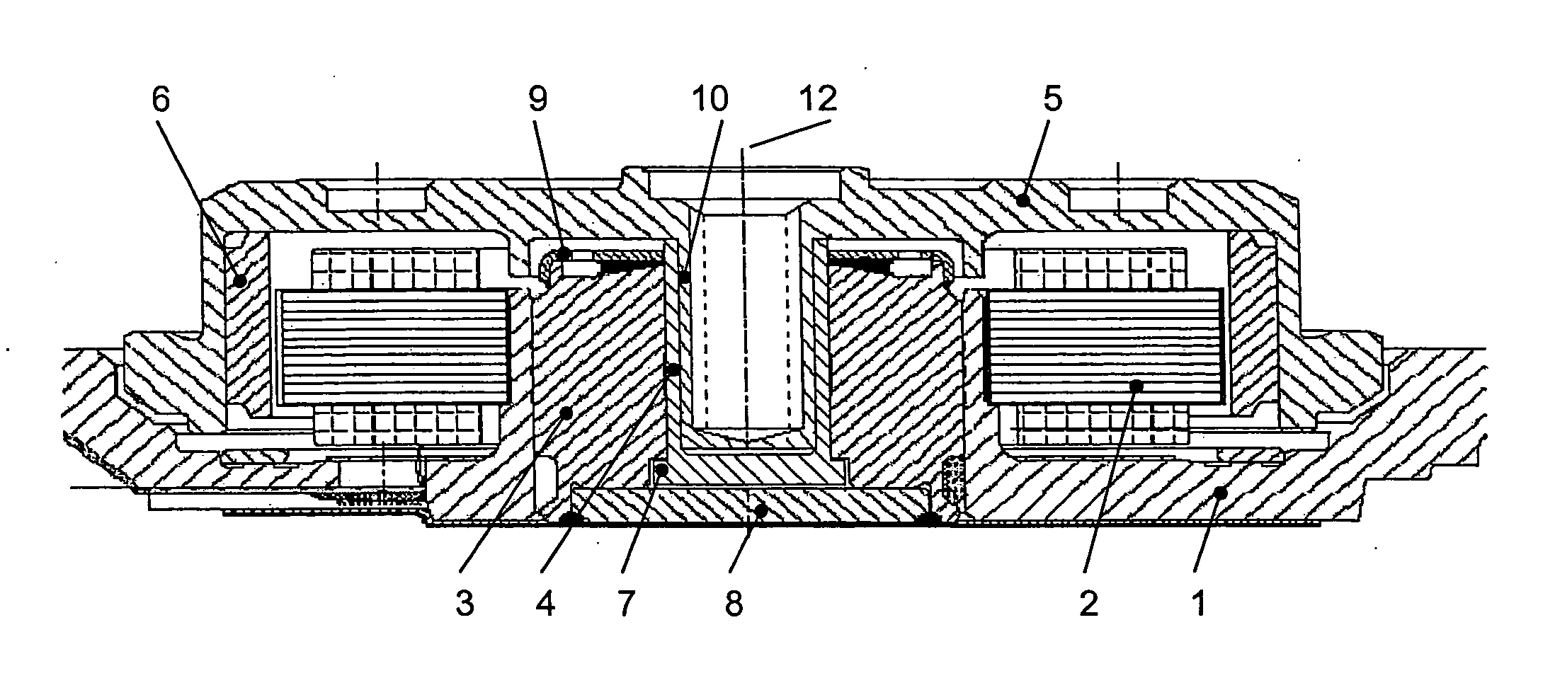
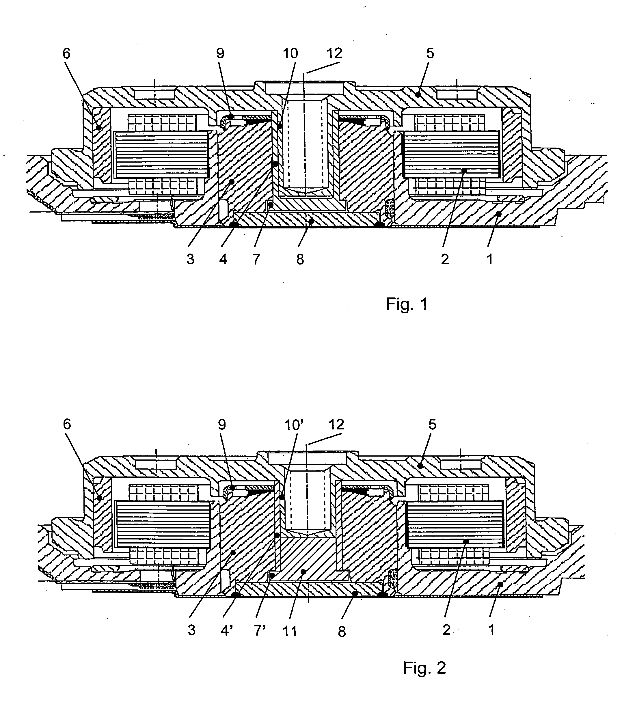
[0020] The drawings show spindle motors having a hydrodynamic bearing system for the purpose of driving platters in hard disk drives. According to the invention, instead of a hydrodynamic bearing system, a roller bearing system could also be provided.

[0021] The spindle motor according to FIG. 1 includes a stationary baseplate 1 on which a stator arrangement 2, comprising a stator core and windings, is arranged. A bearing sleeve 3 is firmly accommodated in a recess in the baseplate 1 and has a cylindrical axial bore in which a shaft, taking the form of a hollow shaft 4 according to the invention, is rotatably accommodated. At one end of the hollow shaft 4 the end face is sealed, whereas the other, free end of the hollow shaft carries a rotor 5 on which one or more platters (not illustrated) of the hard disk drive are arranged and fixed. An annular permanent magnet 6 having a plurality of pole pairs is arranged at the lower inside edge of the rotor 5, an alternating electrical field ...


PUM

PropertyMeasurementUnit
specific diameteraaaaaaaaaa
specific lengthaaaaaaaaaa
diameteraaaaaaaaaa

Abstract

The invention relates to a spindle motor, particularly for the purpose of driving the platters in hard disk drives having a baseplate, a stator arrangement that is stationary with respect to the baseplate, a shaft and a bearing system to rotatably support a rotary driven rotor connected to the shaft. In order to create a spindle motor in which it is possible to connect the shaft to the rotor with a high holding force and improved running precision, provision is made according to the invention for the shaft to be at least partly formed as a hollow shaft and for the rotor to have a shaft shoulder aligned concentric to its rotational axis which is inserted into the hollow shaft and firmly connected to the shaft.

Description

BACKGROUND OF THE INVENTION [0001] The invention relates to a spindle motor particularly for the purpose of driving the platters in hard disk drives according to the preamble of patent claim 1. PRIOR ART [0002] These kinds of spindle motors for hard disk drives comprise a baseplate or a base flange, a stator arrangement that is stationary with respect to the baseplate, a shaft and a bearing system to rotatably support a rotary driven rotor connected to the shaft. The bearing system preferably takes the form of a hydrodynamic bearing system. However, preloaded roller bearing systems can also be used. [0003] The rotor is generally connected to the shaft by means of an interference fit. For this purpose, the rotor is provided with a bore concentric to its rotational axis and having a specific diameter and a specific length into which one end of the shaft is pressfitted. The outside diameter of the shaft is slightly larger than the inside diameter of the rotor bore. This interference is...

Claims


Application Information

Patent Timeline
Patent Type & Authority Applications(United States)
IPC IPC(8): G11B19/20H02K5/16H02K5/167H02K1/28H02K7/00H02K7/08H02K21/22
CPCG11B19/2009H02K7/085H02K7/003H02K5/1675
Inventor BRAUN, DIETERHOFFMANN, JOERG
Owner MINEBEAMITSUMI INC
Why Eureka
Try Eureka