
Display device

a display device and display technology, applied in the direction of identification means, sustainable manufacturing/processing, instruments, etc., can solve the problems of high linear expansivity of plastic substrates, difficult fabrication of drive elements, tfts, etc., and achieve the effect of preventing occurrence and high-quality display

Inactive Publication Date: 2005-06-30
SHARP KK
View PDF9 Cites 22 Cited by
  • Summary
  • Abstract
  • Description
  • Claims
  • Application Information

AI Technical Summary

Benefits of technology

[0010] An object of the present invention is providing a display device having a plastic substrate that includes an inorganic barrier layer and is excellent in surface flatness.
[0019] In the plastic substrate of the display device of the present invention, the planarizing resin layer is formed on the inorganic barrier layer that is formed on the composite layer having the resin-impregnated fiber fabric. Therefore, it is possible to prevent occurrence of the problem that the surface of the inorganic barrier layer becomes uneven in the heating process for forming the inorganic barrier layer on the planarizing resin layer, and thus a flat surface can be obtained. When such a plastic substrate is used for a liquid crystal display device, for example, the resultant device is free from variations in cell thickness due to unevenness of the plastic substrate and thus can provide high-quality display.

Problems solved by technology

However, many problems to be overcome are present to adopt a plastic substrate made of a resin material in a sheet shape as a substrate of a display device.
One of the biggest problems is that a plastic substrate is large in linear expansivity (i.e., coefficient of linear thermal expansion).
Using such a material, therefore, it is difficult to fabricate drive elements, such as TFTs, which require high-precision patterning.
In this case, also, difficulty is found in positioning color filters (and / or a black matrix) formed on the counter substrate with respect to pixel electrodes on the TFT substrate.
According to Literature 2, the composite substrate having the impregnated fiber fabric (woven fabric) disclosed in Literature 1 has a problem that woven portions and intersecting portions of fibers of the fiber fabric cause development of minute unevenness on the substrate surface and this degrades the display quality.
As for the plastic substrate disclosed in Literature 2, fabrication of such a plastic substrate is difficult.
Even if the fabrication is successful, it is difficult to reduce the surface unevenness to the level of 100 nm or less, for example.

Method used


Image

  • Display device
  • Display device
  • Display device

Examples


Embodiment Construction

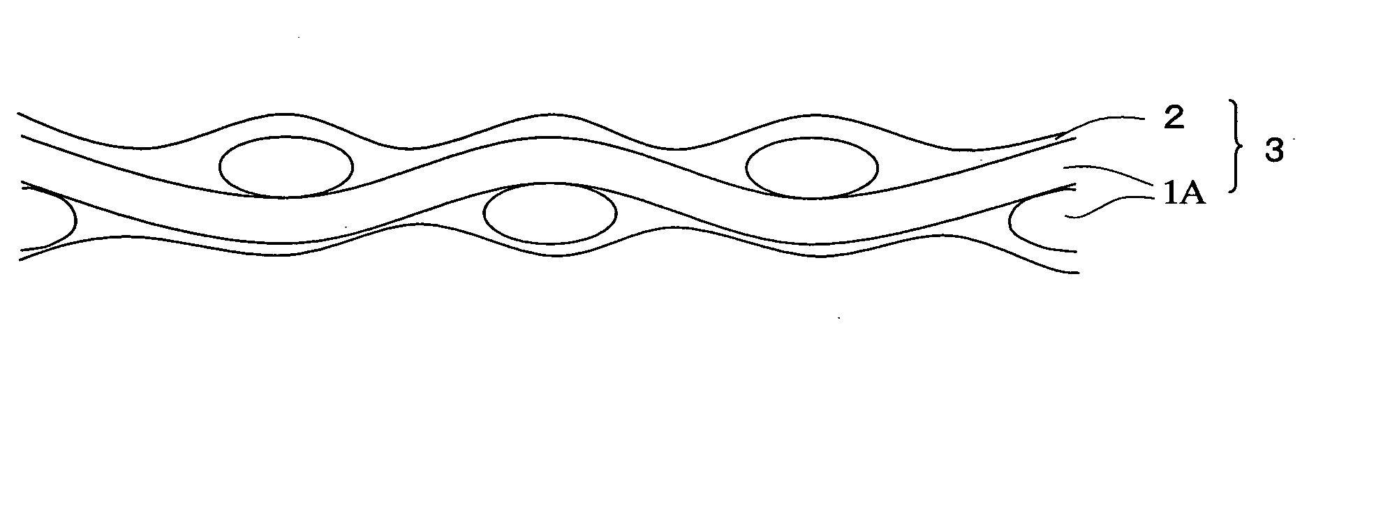
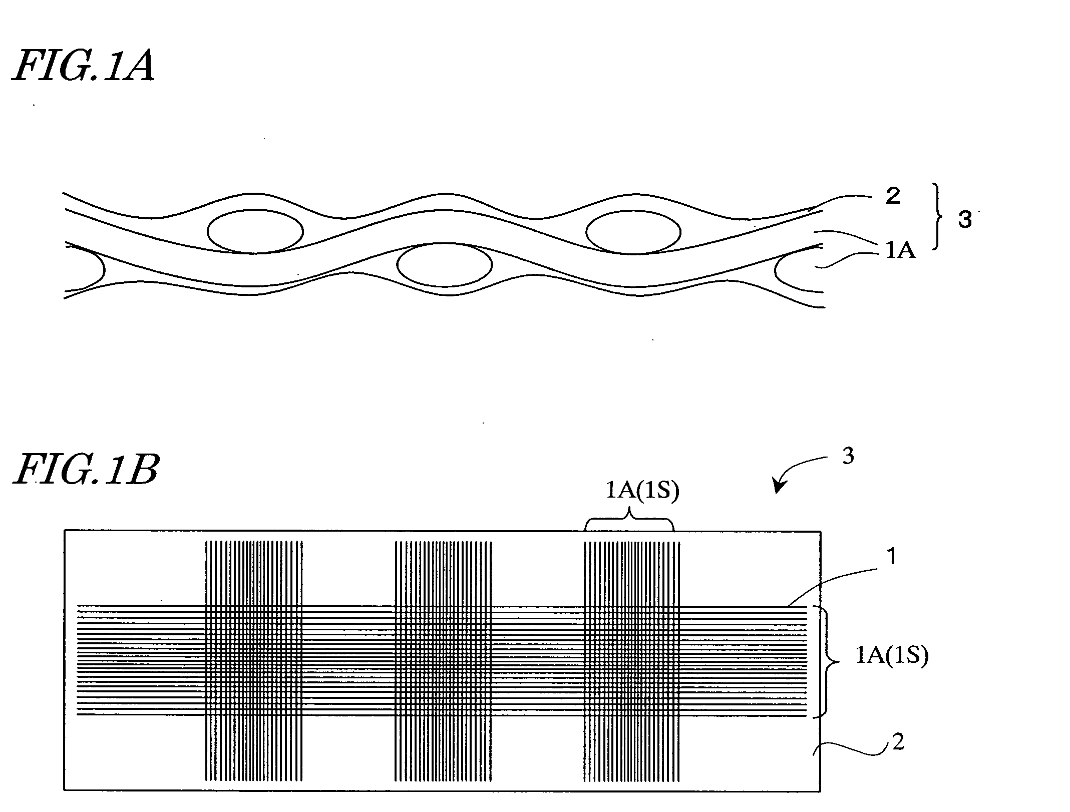
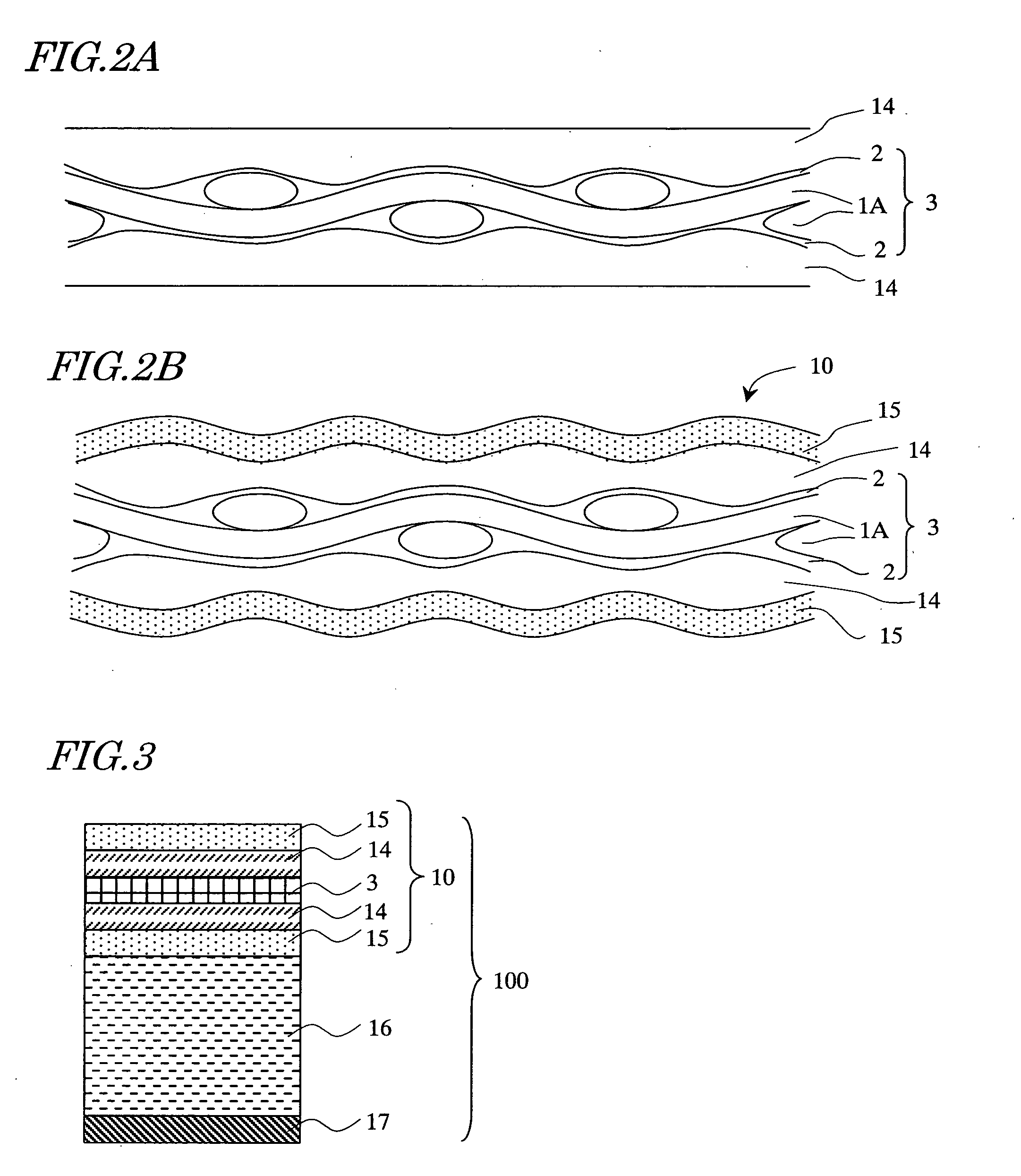
[0027] As mentioned in the prior art description, the present inventors have found a phenomenon that when an inorganic barrier layer is deposited on the surface of a planarizing film of a composite substrate having given flatness, the flatness is lost and unevenness develops on the surface of the inorganic barrier layer. This phenomenon will be described with reference to FIGS. 1A, 1B, 2A and 2B.

[0028]FIGS. 1A and 1B are a cross-sectional view and a plan view, respectively, diagrammatically showing part of a resin-impregnated glass fiber fabric 3.

[0029] The resin-impregnated glass fiber fabric 3 shown in FIGS. 1A and 1B includes a glass fiber fabric 1S and a resin layer 2 covering the glass fiber fabric 1S. The glass fiber fabric 1S is a plain-woven fabric of fiber bundles 1A each composed of a plurality of glass fibers 1. By dipping the glass fiber fabric 1S in an epoxy resin, for example, the resin layer 2 is formed as a thin film covering the surfaces of the glass fiber bundles...


PUM

PropertyMeasurementUnit
Temperatureaaaaaaaaaa
Areaaaaaaaaaaa

Abstract

The display device of the invention includes: a first plastic substrate including a composite layer having a resin-impregnated fiber fabric, an inorganic barrier layer 25 formed on the composite layer, and a planarizing resin layer formed on the inorganic barrier layer; and a display medium layer formed on the planarizing resin layer-side of the first plastic substrate.

Description

BACKGROUND OF THE INVENTION [0001] The present invention relates to a display device having a plastic substrate and a fabrication method therefor, and more particularly, relates to a display device having a fiber-filled plastic substrate. [0002] In recent years, use of liquid crystal display devices and organic EL display devices for portable information terminal equipment has expanded thanks to their features of being thin, light in weight and low in power consumption. With this expansion of the use, there have arisen strong requests that such display devices should be further light and thin and improved in shock resistance and other properties. [0003] To respond to the above requests, an idea of using a plastic substrate instead of the conventionally used glass substrate has been proposed. However, many problems to be overcome are present to adopt a plastic substrate made of a resin material in a sheet shape as a substrate of a display device. [0004] One of the biggest problems is...

Claims


Application Information

Patent Timeline
IPC IPC(8): G02F1/1333G02F1/1335G03F9/00G09F9/30H01L27/32H01L51/00H01L51/50H05B33/02H05B33/10H05B33/14
CPCG02F1/133305H01L27/32H01L51/0096Y10T428/1086Y02E10/549Y10T428/1064H01L51/5253Y10T442/2992Y10T442/3049C09K2323/051C09K2323/06Y02P70/50H10K77/10H10K59/873H10K50/844H10K59/00
Inventor SAIDA, SHINSUKEWATANABE, NORIKO
Owner SHARP KK
Learn More