
Method and system for dynamic resource allocation

a resource allocation and resource technology, applied in the field of computer systems, can solve the problems of inefficiency, waste of resource allocation, and process or thread associated with these applications competing for limited resources,

Inactive Publication Date: 2005-06-30
INTEL CORP
View PDF8 Cites 89 Cited by
  • Summary
  • Abstract
  • Description
  • Claims
  • Application Information

AI Technical Summary

Benefits of technology

[0013] In one embodiment, the invention provides a dynamic allocation of resources for each thread through a feedback system. Inefficiencies encountered by conventional systems may be reduced and the overall performance may be improved while the overall power usage of a multi-threaded microprocessor may be reduced.

Problems solved by technology

As a computer system processes the one or more applications, processes or threads associated with these applications may compete for limited resources.
Inefficiencies may arise when resources are statically partitioned or allocated.
This may occur if one thread does not need that particular resource as much as the other does and so its allocation of the resource is wasted while the other thread could use it.
If a computer system is not fully using all its resources it may deliver lower overall system performance.
Although the audio application will require sufficient resources so that the application offers good sound quality, some resources allocated for threads associated with the audio application may be wasted.
When resources are fully shared among threads, fairness issues can arise resulting in similar inefficiencies.
One thread that allocates the resource faster but not necessarily for the execution of useful micro-ops can take over most of the resource, in expense of the other thread(s) that may be doing more useful tasks.

Method used


Image

  • Method and system for dynamic resource allocation
  • Method and system for dynamic resource allocation
  • Method and system for dynamic resource allocation

Examples


Embodiment Construction

[0012] Embodiments of the present invention provide a system and method for dynamic resource allocation in a computer system. The invention may provide a technique for allocating resources efficiently so that the system can achieve optimal performance. Embodiments of the present invention provide a system that dynamically allocates resources to, for example, threads so that resources are efficiently and optimally used.

[0013] In one embodiment, the invention provides a dynamic allocation of resources for each thread through a feedback system. Inefficiencies encountered by conventional systems may be reduced and the overall performance may be improved while the overall power usage of a multi-threaded microprocessor may be reduced.

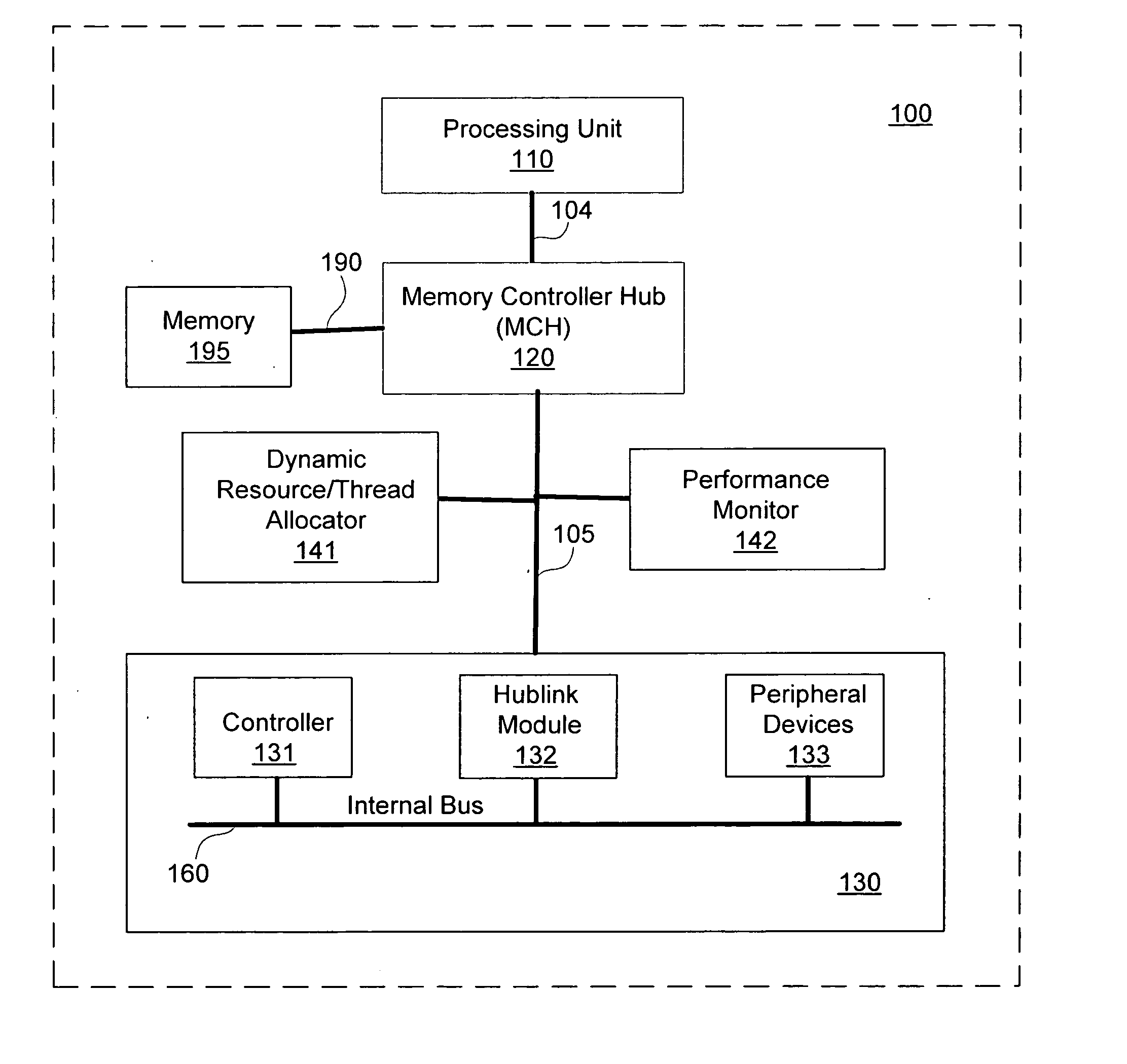
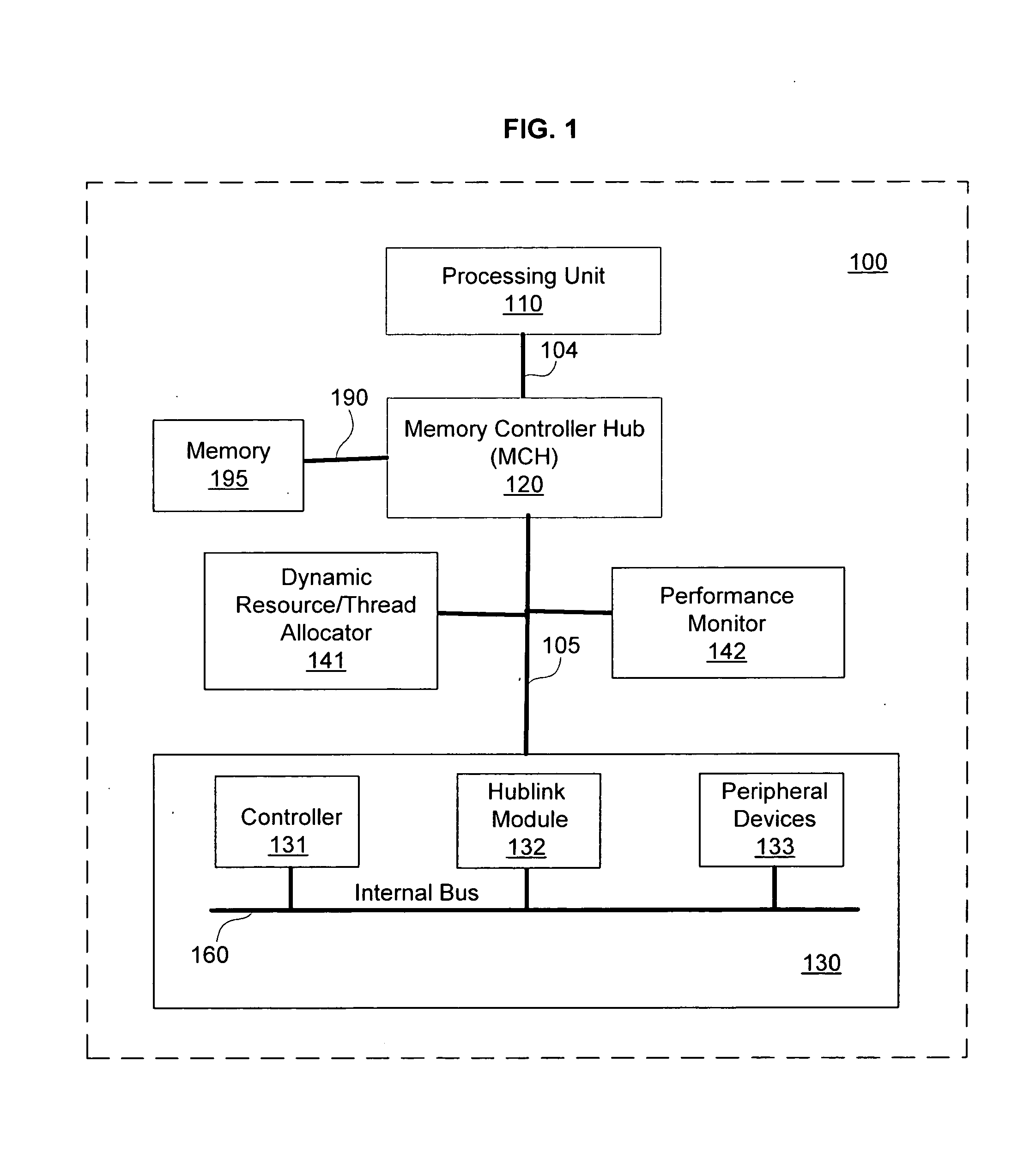
[0014]FIG. 1 is a partial block diagram of a system 100 in which the embodiments of the present invention find application. As shown in FIG. 1, the system 100 may be a partial representation of computer and / or any other device including these components. Sy...


PUM


Abstract

Embodiments of the present invention provide a dynamic resource allocator to allocate resources performance optimization in, for example, a computer system. The dynamic resource allocator to allocate a resource to one or more threads associated with an application based on a performance rate. Embodiments of the present invention may further include a performance monitor to monitor the performance rate of the one or more threads. The dynamic resource allocator to allocate an additional resource to the one or more threads, if the thread is performing above a performance threshold. In embodiments of the present invention, the dynamic resource allocation strategy may be decided based on, for example, optimizing the overall system throughput, minimizing power consumption, meeting system performance goals (e.g., real time requirements), user specified performance priorities and / or application specified performance priorities.

Description

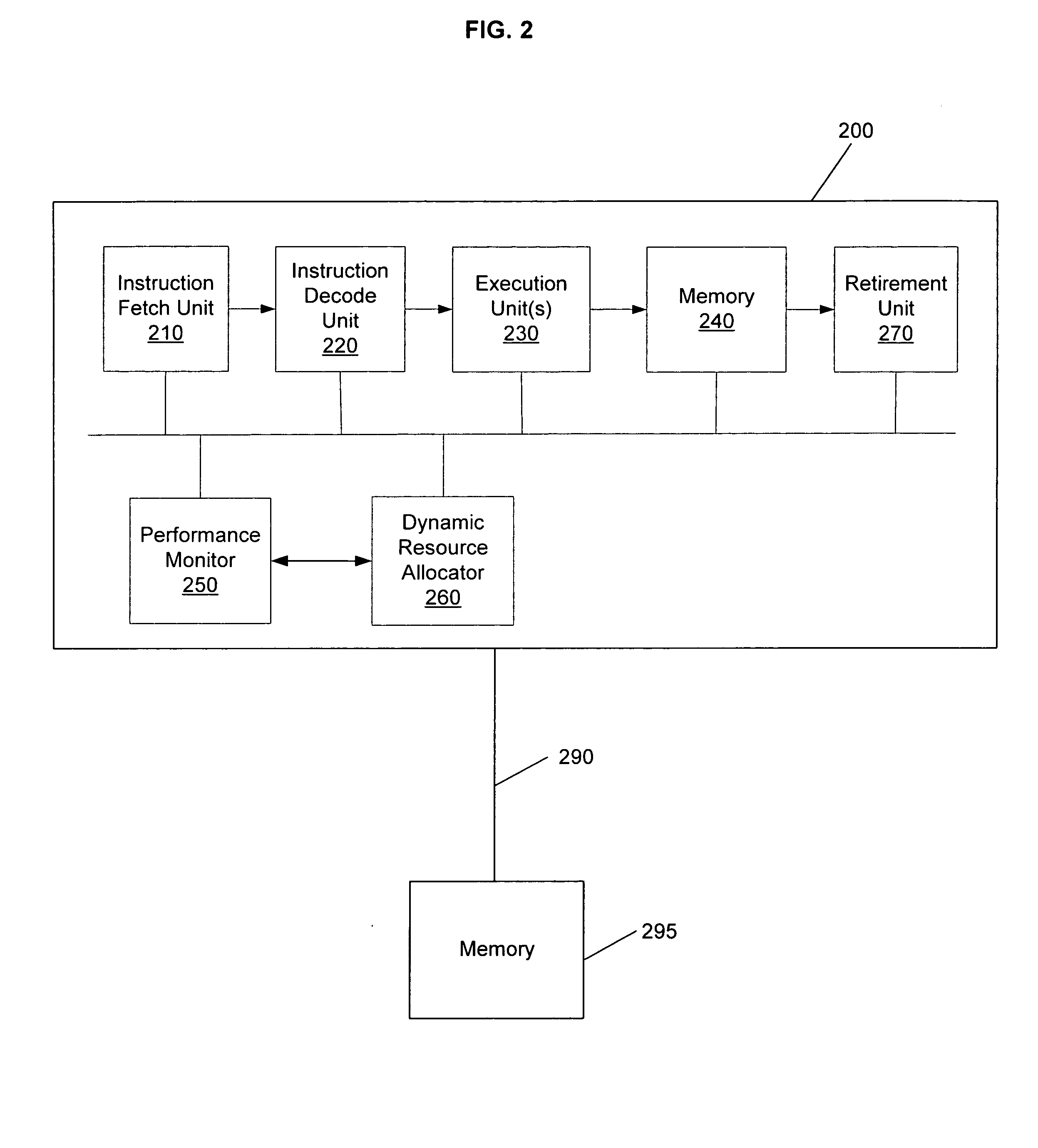
TECHNICAL FIELD [0001] The present invention relates to computer systems. More particularly, the present invention relates to allocation of resources between threads in a computer system that supports simultaneous multi threading. BACKGROUND OF THE INVENTION [0002] A typical computer system consists of several basic components and / or resources, including a processor, volatile and non-volatile memory, and various peripheral devices, including graphics controller(s), mass storage devices, and input / output devices. A chipset connects these computer system components together, and manages the flow of information between them. Known protocols may be used by the computer system for communications among system components. [0003] Moreover, a processor in a computer system may include a plurality of different units such as instruction fetch unit, decode unit, execute unit, memory unit, retirement unit, etc. These units may include an instruction pipeline that processes instructions. These un...

Claims


Application Information

Patent Timeline
IPC IPC(8): G06F9/50H04J3/16
CPCY02B60/142G06F9/5011Y02D10/00
Inventor HAMMARLUND, PER H.OZGUL, MELIH
Owner INTEL CORP
Learn More