[0003] It is an object of the present invention to provide a self-standing bag which maintains the self-standing performance until the content is used up, can be reduced in volume by folding in case of disposing of the bag, and has a high fixing strength of a spout, and a method of manufacturing such a self-standing bag.
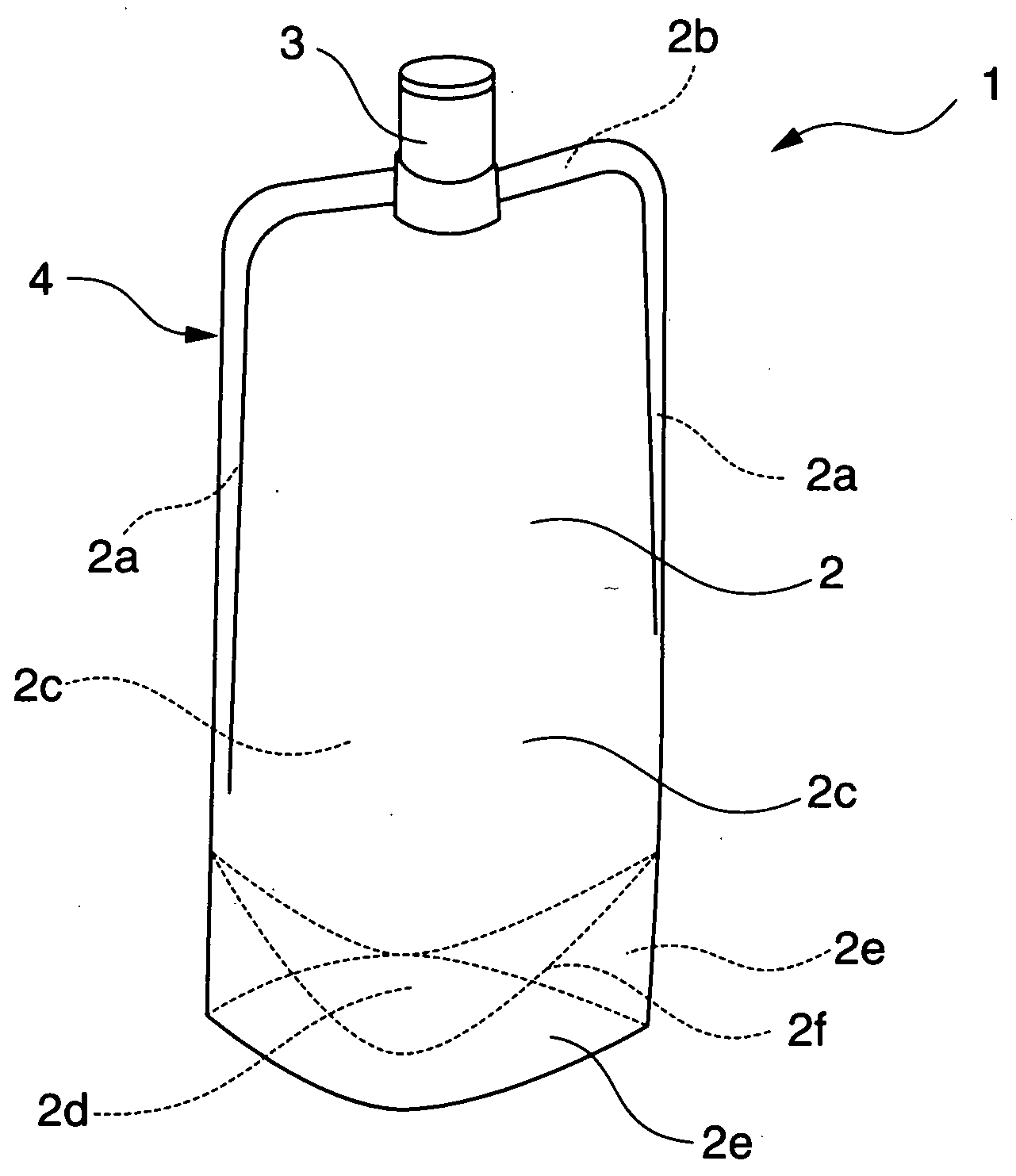
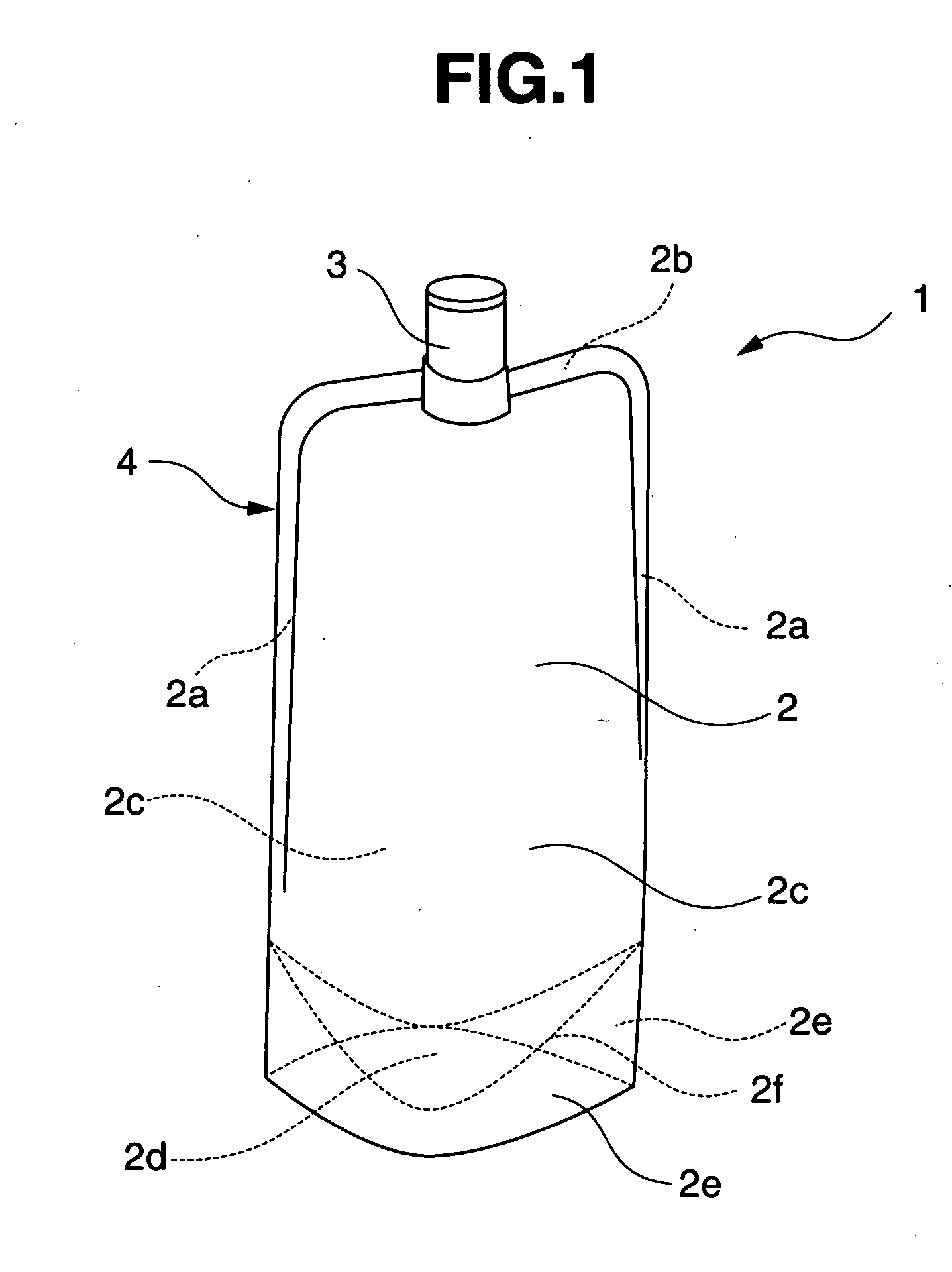
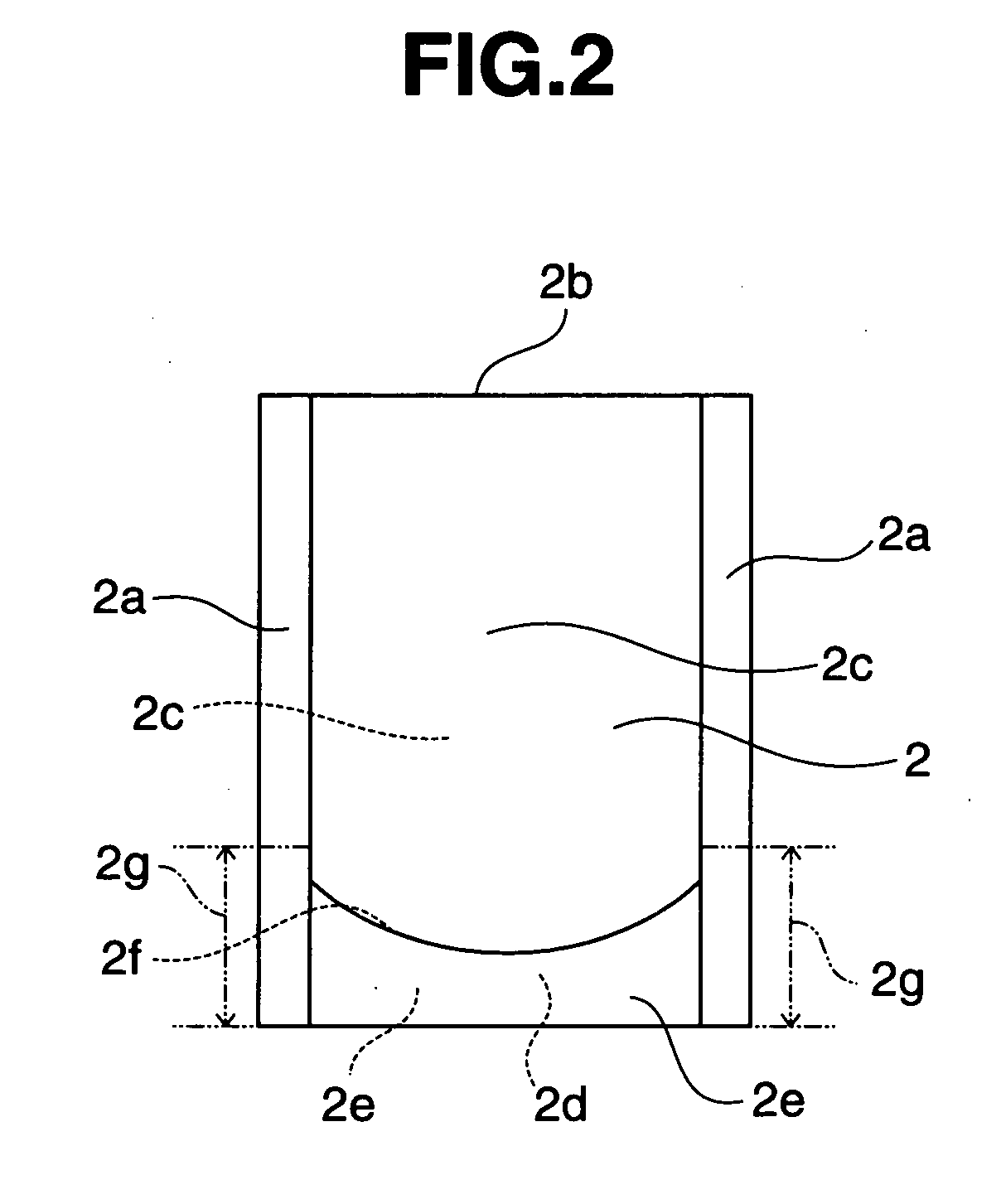
[0006] The inventive self-standing bag comprises a bag body composed of two body films and a bottom film folded down in a reverse V-shape at the bottom portion, and a spout at an upper portion of the bag body, said bag body having fusion bonding parts at the lower edges and at least a part of each side edge to which the bottom film is present so that at least the bottom film is fixed with both the body films, and a frame of a reverse-recessed shape integrally molded with the spout being attached from the upper edge to each side edge of the bag body. Accordingly, the parts of the frame present at each side edge of the bag body constitute so-called ribs to the bag body and function as supports of the bag body, thereby improving the self-standing property of the bag body. Although the spout is provided at the upper portion of the bag body, the self-standing performance can be sufficiently maintained until the content is completely used up. In addition, since the spout is integrally molded with the frame, the bag is excellent in the
attachment strength of the spout. Moreover, a variety of spouts can be easily attached securely.
[0008] The frame in the present invention may be attached to the bag body so as to extend over the entire length of the range from the upper edge to both side edges of the bag body, as will be described later. However, when the frame is attached to the bag body at a part of each side edge to which the fusion bonding parts is present so that a part or the whole of each fusion bonding is left, the self-standing performance can be assured by spreading the bottom film, and the amount of the resin used for molding the frame can be reduced, thereby leading to a lighter weight. In addition, the parts the bag body free of the frame become easier to fold, and the bag becomes easier to
scrap. Therefore, such a configuration is preferable.
[0010] In the method of manufacturing the self-standing bag, the films constituting the bag body are formed as a self-standing shape. And the lower edges and at least a part of each side edge to which the bottom film is present are joined by fusion bonding so that at least the bottom film is fixed with the two body films, and thereafter the frame is attached to the bag body so that the spout is integral with the frame, thereby preparing a self-standing bag having the spout. Accordingly, even when the lower edges and only the lower parts of the side edges are fusion bonded so that only the bottom film is fixed to the body films of the bag body in the manufacture of the self-standing bag according to the present invention, the upper edge which is an unjoined edge and the unjoined parts of the side edges can be joined with the frame upon the attachment of the frame to the bag body, thereby obtaining a self-standing bag having the spout. Even when the bag body is formed in such a weak joining strength as that the parts except the lower parts of the side edges barely keep the bag shape, the attachment of the frame can reinforce the joining strength, thereby easily and surely joining the edges of the bag body. More specifically, the bag body may be formed completely or incompletely into a bag shape so long as the bottom film is fusion bonded. It is preferred as the method of manufacturing the self-standing bag according to the present invention to use the bag body completely formed into a bag shape, whereby the resulting self-standing bag becomes excellent in strength. The attachment of the spout and the frame is conducted more easily and surely.
[0012] The self-standing bag according to the present invention is flexible and has good self-standing performance, so that the bag functions as a self-standing packing bag and fulfills the self-standing performance until the contents are completely consumed upon use in
spite that the spout is attached, and the bag can be disposed by rolling up the bag with a reduction in volume after the completion of use. Further, the self-standing bag is high in fixing strength of the spout to the bag. It is also possible to reinforce the joining strength. Therefore, the self-standing bag according to the present invention is easy to use, is excellent in strength as a packing bag, and is easy to reduce in volume in case of disposing the bag after the completion of use, which is suited to
environmental protection. According to the method of manufacturing the self-standing bag of the present invention, the self-standing bag having the above-mentioned characteristics and particularly having an excellent seal strength of the bag body can be manufactured easily and securely.

