Heat spreader for display device

a technology of display device and heat spreader, which is applied in the direction of identification means, electrical apparatus casings/cabinets/drawers, semiconductor/solid-state device details, etc., can solve the problems of large voltages for activation becoming more susceptible to thermal deterioration, difficult heat conduction in directions parallel to the panel face, and difficult to achieve good thermal contact, prevent or reduce the possibility of graphite particles flaking off, and sufficient volume

Active Publication Date: 2005-06-30
NEOGRAF SOLUTIONS LLC
View PDF30 Cites 18 Cited by
  • Summary
  • Abstract
  • Description
  • Claims
  • Application Information

AI Technical Summary

Benefits of technology

[0022] Another object of the present invention is to provide a heat spreader material which can be applied to a heat source or collection of heat sources such as a plasma display panel or light emitting diode and adhere with good thermal contact between the heat spreader and the device.
[0023] Still another object of the present invention is to provide a heat spreader material which is isolated to prevent or reduce the possibility of graphite particles flaking off.
[0024] Yet another object of the present invention is to provide a heat spreader which can adhered and removed from a heat source with minimal damage to the spreader or the source.
[0025] A further object of the present invention is to provide a heat spreader which can be produced in sufficient volume and in a cost effective manner.
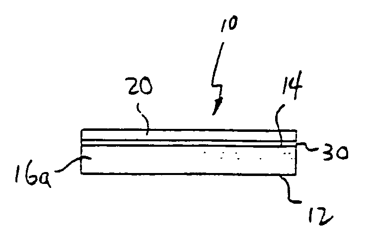
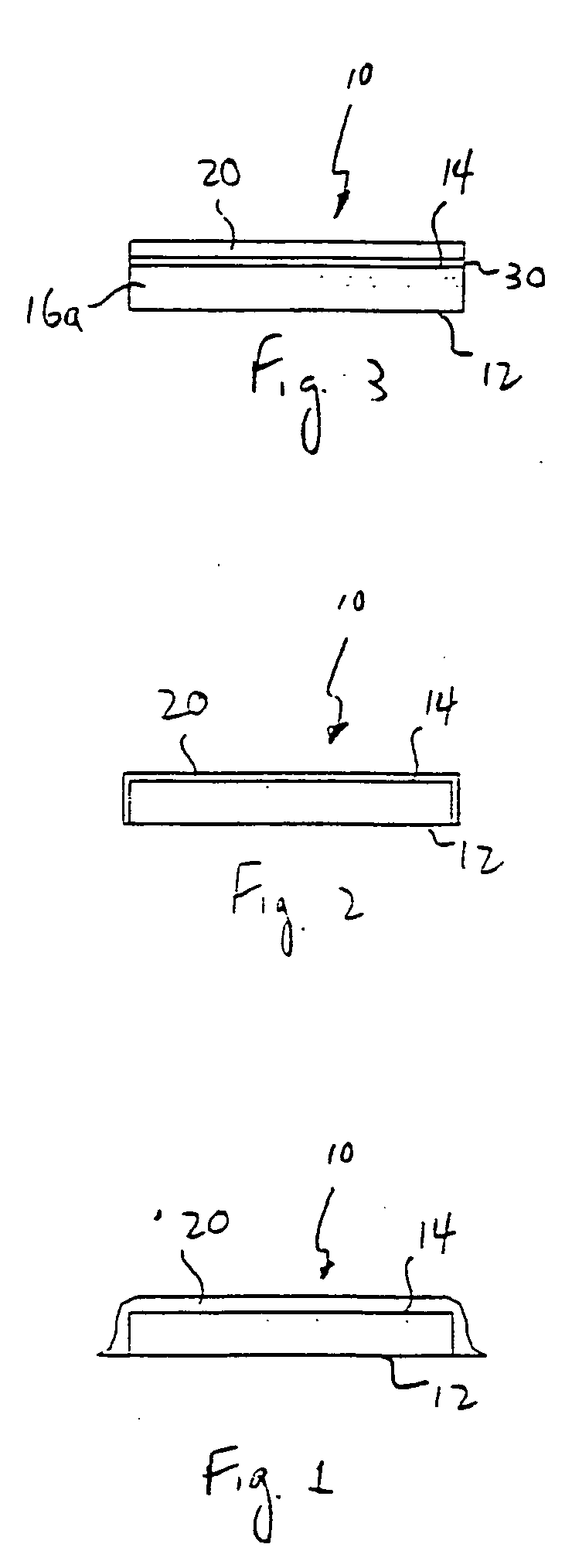
[0026] These objects and others which will be apparent to the skilled artisan upon reading the following description, can be achieved by providing a heat spreader for a display device, comprising at least one sheet of compressed particles of exfoliated graphite having a surface area greater than the surface area of that part of the device, such as a discharge cell, facing the back surface of the device. The display device can be an emissive display device such as plasma display panel or a light-emitting diode panel, or another type of display device such as a liquid crystal display device. More preferably, the at least one sheet of compressed particles of exfoliated graphite has a surface area greater than the surface area of that part of a plurality of discharge cells facing the back surface of the device. Advantageously, the heat spreader is a laminate comprising a plurality of sheets of compressed particles of exfoliated graphite, and has a protective coating thereon to prevent flaking of graphite particles therefrom. In a preferred embodiment, the surface of the heat spreader has a facing sheet, such as an aluminum or copper sheet thereon, to further seal the heats spreader and facilitate rework.
[0027] In a preferred embodiment, the heat spreader has an adhesive thereon and a release material positioned such that the adhesive is sandwiched between the heat spreader and the release material. The release material and adhesive are selected to permit a predetermined rate of release of the release material without causing undesirable damage to the heat spreader. Indeed, the adhesive and release material provide an average release load of no greater than about 40 grams per centimeter at a release speed of one meter per second, more preferably no greater than about 10 grams per centimeter at a release speed of one meter per second.

Problems solved by technology

The heat generated in the discharge cells is transferred to the glass forming the base plates, but heat conduction in directions parallel to the panel face is difficult because of the properties of the glass base plate material.
Further, since the temperature difference between activated and nonactivated discharge cells can be high, and the temperature difference between discharge cells generating white light and those generating darker colors also can be high, a stress is applied to the panel unit, causing the conventional plasma display panel to be prone to cracks and breakage.
Thus, those cells having large voltages for activation become more susceptible to thermal deterioration and tend to exacerbate the breakage problem of the panel unit of the plasma display panel.
LEDs present similar issues with respect to heat generation as do PDPs.
Similar issues arise in display devices other than emissive display devices, such as LCDs, where hot spots can limit the effectiveness or life of the device.
However, there is a concern in the electronics industries in general that the use of graphite-based materials can result in graphite particles flaking off, with the result that the flakes can mechanically (i.e., in the same manner as dust particles) interfere with equipment operation and function and, more significantly, that due to the conductive nature of graphite, graphite flakes can electrically interfere with operation of the emissive display device.
Although it is believed that it has been shown that these concerns are misplaced, they still survive.
Also, the use of adhesives to attach a graphite heat spreader to an emissive display device can be disadvantageous at times. More specifically, in the event rework (i.e., removal and replacement of the heat spreader) is needed, the adhesive bond can be stronger than the structural integrity of the graphite sheet; in this situation, the graphite sheet cannot always be cleanly lifted off the panel without the use of scrapers or other like tools, which can be time consuming and potentially damaging to the graphite sheet, the panel or both.

Method used


Image

  • Heat spreader for display device
  • Heat spreader for display device
  • Heat spreader for display device

Examples


example 1

[0096] The thermal properties of a Panasonic plasma TV model number TH42PA20 using an acrylic thermal spreader attached to the back of the plasma display panel are analyzed under the following different screen conditions. Patterns of white and black are generated on the display and the screen surface temperatures measured using an infra-red camera. In all cases the background is black. Patterns consisted of: 1) three white lines evenly spaced horizontally across the screen (23.9% screen illumination) and; 2) a 4×3 array of evenly spaced white dots (4% screen illumination). After testing the unit with the conventional acrylic thermal spreader, the acrylic spreader is removed and replaced with a flexible graphite thermal spreader 1.4 mm thick and having an in-plane thermal conductivity of approximately 260 W / m° K. The plasma display is then re-tested under identical conditions as previously stated, and the results set out in Table 1.

TABLE 1WhiteThermalPattern TPatternSpreaderTmaxRan...

example 2

[0097] The thermal properties of a NEC plasma display model Plasmasync 42″ 42XM2 HD using an aluminum / silicone thermal spreader attached to the back of the plasma display panel are analyzed under the following different screen conditions. Patterns of white and black are generated on the display and the screen surface temperatures are measured using an infra-red camera. In all cases the background is black. Patterns consisted of: 1) three white lines evenly spaced horizontally across the screen (23.9% screen illumination) and; 2) a 4×3 array of evenly spaced white dots (4% screen illumination). After testing the unit with the conventional aluminum / silicone thermal spreader, the aluminum / silicone thermal spreader is removed and replaced with a flexible graphite thermal spreader 1.4 mm thick and having a thermal conductivity of approximately 260 W / m° K. The display is then re-tested under identical conditions, and the results set out in Table 2.

TABLE 2WhitePattern TPatternThermal Spr...


PUM

PropertyMeasurementUnit
speedaaaaaaaaaa
thicknessaaaaaaaaaa
thicknessaaaaaaaaaa

Abstract

A heat spreader (10) for a display device, such as a plasma display panel, a light emitting diode or a liquid crystal display, comprising at least one sheet of compressed particles of exfoliated graphite having a surface area greater than the surface area of that part of the back surface of the display device where a localized region of higher temperature is generated.

Description

RELATED APPLICATIONS [0001] This application is a continuation-in-part of copending and commonly assigned U.S. patent application Ser. No. 10 / 685,103, filed in the names of Norley, Smalc, Capp, and Clovesko on Oct. 14, 2003, entitled “Heat Spreader for Plasma Display Panel,” and co-pending and commonly assigned U.S. patent application Ser. No. 10 / 844,537, filed in the names of Clovesko, Norley, Smalc and Capp on May 12, 2004, entitled “Heat Spreader for Emissive Display Device,” and copending and commonly assigned U.S. patent application Ser. No. 10 / 897,308, filed in the names of the Clovesko, Norley, Smalc and Capp on Jul. 22, 2004, entitled “Heat Spreader for Emissive Display” disclosures of which are incorporated herein by reference.TECHNICAL FIELD [0002] The present invention relates to a heat spreader useful for an display device, such as a plasma display panel (PDP), a liquid crystal display (LCD), a light emitting diode (LED), and the like, and the unique thermal issues occas...

Claims


Application Information

Patent Timeline
Patent Type & Authority Applications(United States)
IPC IPC(8): B32B43/00G06F1/20H01J17/28H01J17/49H05K5/00H05K7/20
CPCB32B9/00G06F1/1601G06F1/20G06F2200/1612H01J2211/66H01L23/367Y10T428/1438H01L2924/0002H05K7/20963Y10T428/30Y10T428/14H01L2924/00H01J17/28G09F9/00B32B2307/302B32B7/12B32B2457/20B32B9/007B32B9/045B32B9/041
Inventor CLOVESKO, TIMOTHYNORLEY, JULIANSMALC, MARTIN DAVIDCAPP, JOSEPH PAUL
Owner NEOGRAF SOLUTIONS LLC
Why Eureka
Try Eureka