Plasma processing apparatus

Inactive Publication Date: 2005-07-07
PANASONIC CORP
View PDF1 Cites 171 Cited by
  • Summary
  • Abstract
  • Description
  • Claims
  • Application Information

AI Technical Summary

Benefits of technology

[0059] Further, since the liquid temperature adjusting unit is placed outside the liquid storage portion and since the plasma processing apparatus further comprises a liquid flow passage communicated with the liquid storage portion and a liquid circulating unit for circulating the electrically insulative liquid through the liquid flow passage, the degree of freedom for the installation of the liquid temperature adjusting unit can be enhanced, so that the cooling or heating performance can be enhanced. As such a liquid temperature adjusting unit shown above, applicable are commercially available articles called chiller, circulator or thermostat, producing an advantage of high availability.
[0060] Further, the liquid storage portion has a generally closed small capacity so that the storage volume of the electrically insulative liquid (e.g., electrically insulative fluorine inert oil or organic oils) to be stored in the liquid storage portion is made small, thus allowing the cost therefor to be reduced. Also, such a small capacity of the liquid storage portion makes it unlikely to occur that the stored electrically insulative liquid may leak. Further, in the heat exchange unit, the fluid to be stored so as to be separable from the electrically insulative liquid may be a fluid having no electrically insulation property, e.g. water (one other than pure water), instead of the electrically insulative liquid, allowing the cost required for the electrically insulative liquid to be reduced also from such a viewpoint.
[0061] Further, since there is no need for providing the liquid temperature adjusting unit of separate installation outside the liquid storage portion, th

Problems solved by technology

Repeated execution and halt of plasma processing shown above causes the atmosphere within the plasma processing region R to be unstable (unsteady), and increasing a thickness of the deposited film with increasing number of times of processing leads to change of the atmosphere.
This gives rise to an issue that plasma processing of high repeatability cannot be implemented.
Further, repeating such plasma processing and plasma halt causes the quartz of the bell jar 502 and the deposited fil

Method used


Image

  • Plasma processing apparatus
  • Plasma processing apparatus
  • Plasma processing apparatus

Examples


first embodiment

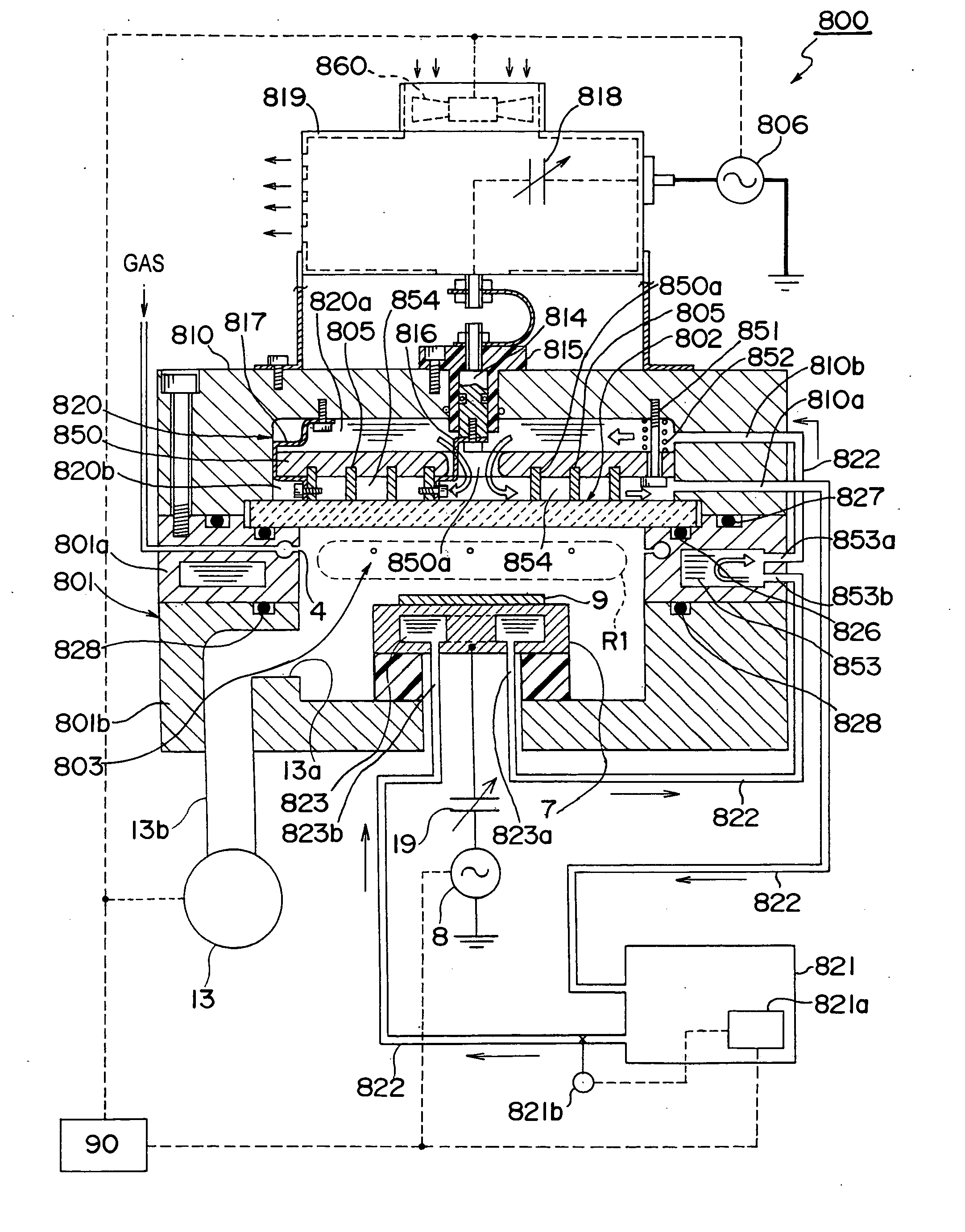
[0080] A schematic sectional view of a plasma processing apparatus 800 which is an example of a plasma processing apparatus according to a first embodiment of the present invention is shown in FIG. 1.

[0081] As shown in FIG. 1, the plasma processing apparatus 800 is equipped with a vacuum vessel 801 which has an opening at the top thereof and generally cylindrical shaped, and a dielectric window (quartz plate) 802 which is formed of a generally disc-shaped dielectric material (e.g., quartz) and which is provided so as to close the opening at the top of the vacuum vessel 801, where a processing chamber 803 is formed which is a space closed by the vacuum vessel 801 and the dielectric window 802 and a space where plasma processing is performed.

[0082] Further, as shown in FIG. 1, the vacuum vessel 801 is divided into a lower vacuum vessel 801b, which is a lower part of the generally cylindrical-shaped bottomed member, and an upper vacuum vessel 801a, which is its upper portion and annu...

second embodiment

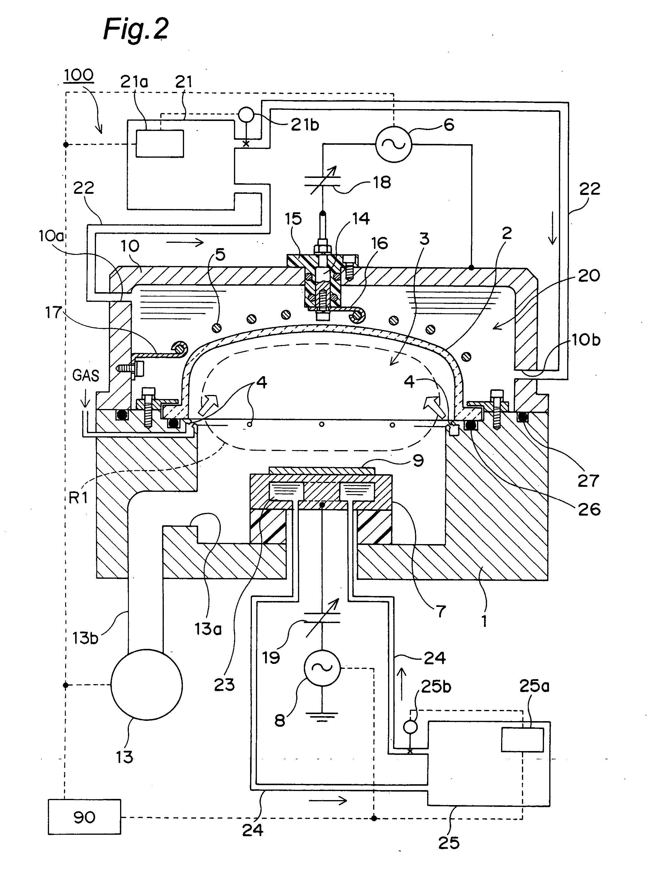
[0116] It is noted here that the present invention is not limited to the foregoing embodiment, and may be carried out in other various aspects. For instance, FIG. 2 shows a schematic sectional view of a plasma processing apparatus 100 which is an example of a plasma processing apparatus according to the second embodiment of the present invention. As shown in FIG. 2, the plasma processing apparatus 100 is different in construction from the plasma processing apparatus 800 of the first embodiment structurally in terms of having not the disc-shaped dielectric window 802 but a generally hemispherical-shell shaped dielectric window 2, but generally similar in construction to the plasma processing apparatus 800 in terms of the other structural components unrelated to the form of the dielectric window 2. The following description is given about this different construction. In addition, for an easier understanding of the description, constituent parts similar to those of the plasma processin...

third embodiment

[0133] Next, FIG. 5 is a schematic sectional view of a plasma processing apparatus 200 according to a third embodiment of the present invention. As shown in FIG. 5, the plasma processing apparatus 200 is different in construction from the plasma processing apparatus 100 of the second embodiment structurally in terms of having not the generally hemispherical-shell shaped dielectric window 2 but a generally plate-shaped dielectric window 202, but similar in construction to the plasma processing apparatus 100 in terms of the other structural components unrelated to the form of the dielectric window 202. Further, as shown in FIG. 5, the plasma processing apparatus 200 is similar in construction to the plasma processing apparatus 800 in terms of having the generally disc-shaped window 202, but different in terms of placing a liquid flow passage 220 and a coil 205 in the inside of the dielectric window 202. This different construction only is explained below. In addition, for an easier un...


PUM

PropertyMeasurementUnit
Electrical resistivityaaaaaaaaaa
Temperatureaaaaaaaaaa
Dielectric polarization enthalpyaaaaaaaaaa

Abstract

A plasma processing apparatus has a liquid storage vessel which is formed outside of a dielectric window and in which a plasma-exciting coil or electrode is placed inside and moreover in which an electrically insulative liquid is stored in the inside of the liquid storage vessel, as well as a cooling unit and a heating unit for the liquid. Temperature of the liquid stored in the liquid storage portion is adjusted, by which temperature of the plasma-exciting coil or electrode and the dielectric window is controlled via the liquid.

Description

BACKGROUND OF THE INVENTION [0001] The present invention relates to plasma processing apparatuses such as dry etching apparatuses and plasma CVD apparatuses to be used for the manufacture of semiconductor or other thin-film circuits and electronic components or boards on which those electronic circuits and others are to be mounted. [0002] Conventionally, as one of the plasma processing apparatuses to be used for the manufacture of semiconductor or other thin-film circuits, electronic components, or boards, there has been a plasma processing apparatus of the RF (Radio Frequency) plasma excitation method in which RF power is applied to a plasma-exciting coil or electrode positioned outside a vacuum vessel to excite a plasma in the vacuum vessel, and plasma processing is performed on a substrate (work piece) set within the vacuum vessel with the excited plasma. The plasma processing apparatus of this method is so designed with an RF magnetic field generated outside of the vacuum vessel...

Claims


Application Information

Patent Timeline
IPC IPC(8): H01J37/32H01L21/3065
CPCH01J37/321H01L21/3065H01J37/32522
Inventor SUZUKI, MASAKI
Owner PANASONIC CORP
Why Eureka
Try Eureka