

Booster and motor controller
a motor controller and booster technology, applied in the field of boosters, can solve the problems of increasing losses, steady-state loss, poor fuel economy, etc., and achieve the effect of reducing switching losses
- Summary
- Abstract
- Description
- Claims
- Application Information
AI Technical Summary
Benefits of technology
Problems solved by technology
Method used
Image

Examples
first preferred embodiment
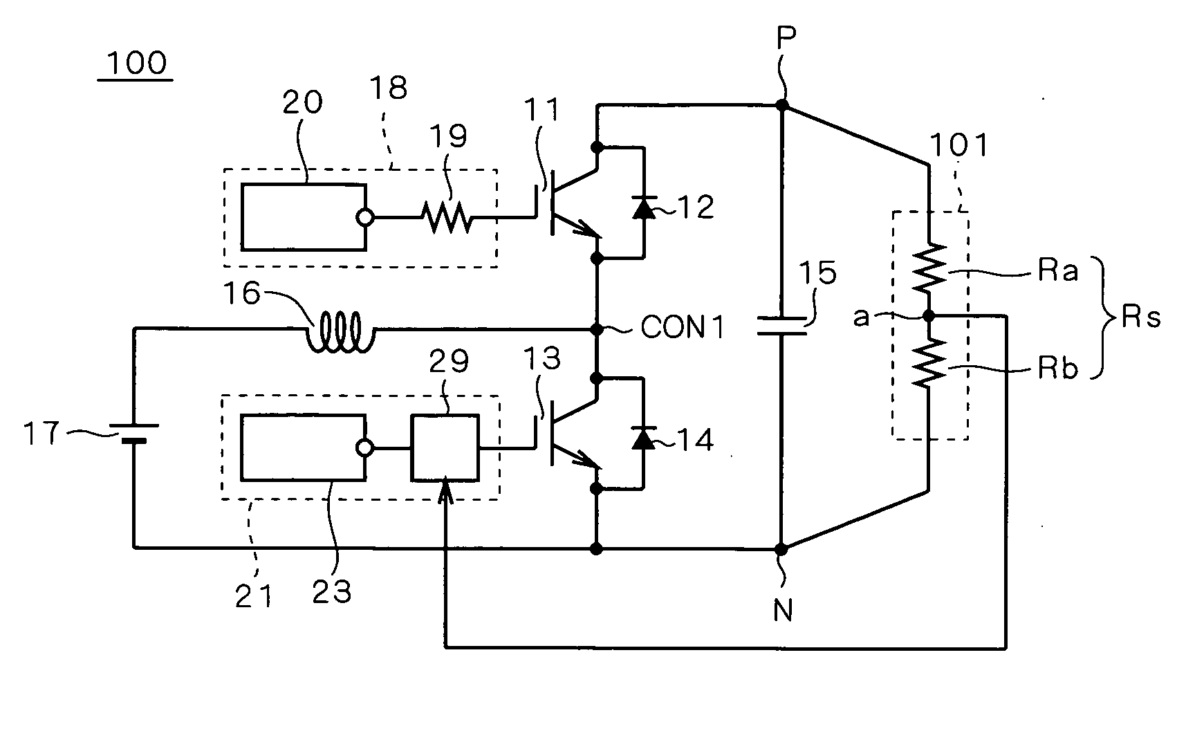
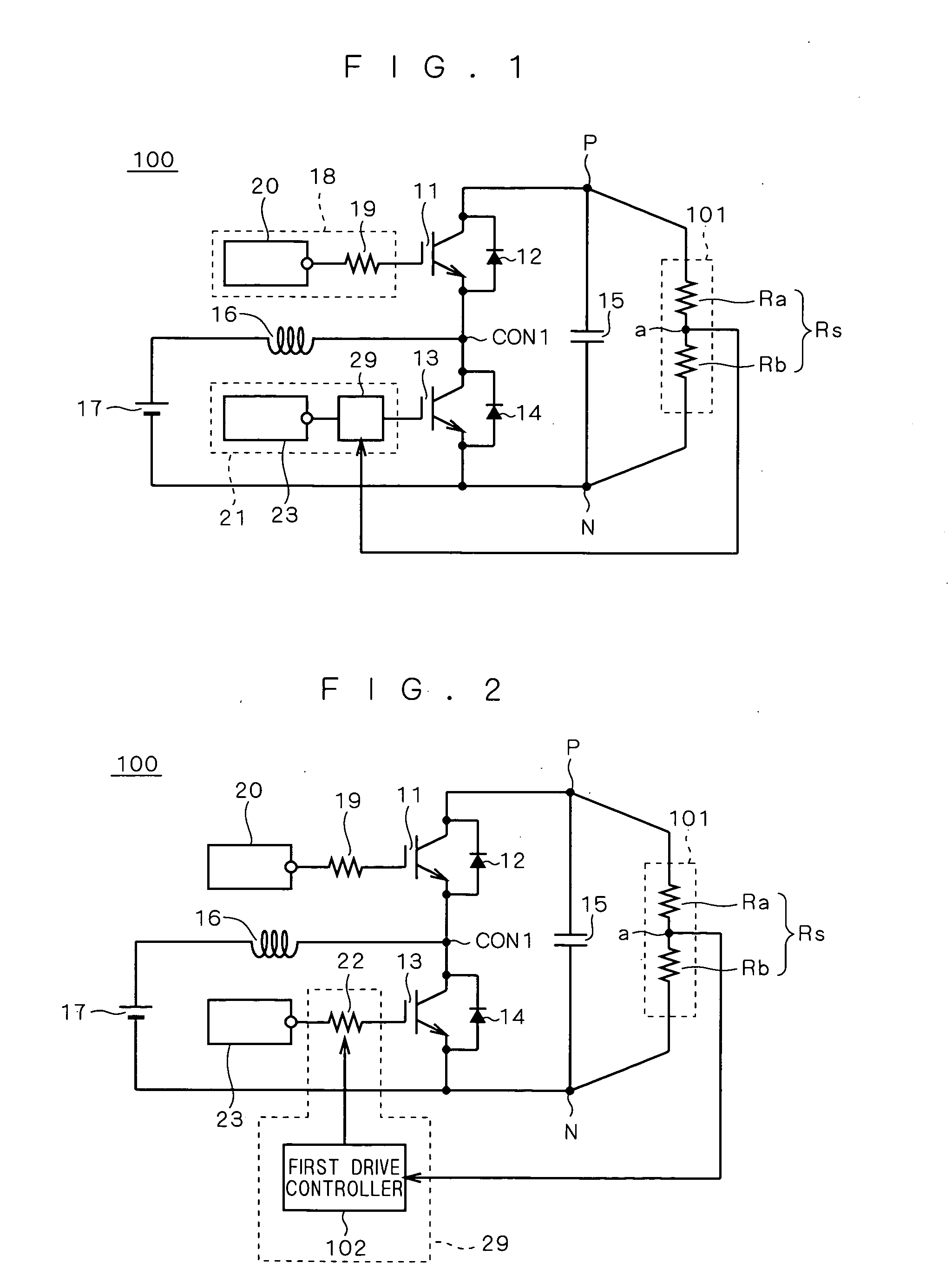
[0030]FIGS. 1 and 2 both show the configuration of a booster 100 according to a first preferred embodiment of the present invention. The booster 100 comprises IGBTs (insulated gate bipolar transistors) as switching elements. An IGBT 11 has a collector connected to the cathode of a free wheeling diode 12. The collector of the IGBT 11 is further connected at an output terminal P to one end of a capacitor 15. The IGBT 11 has an emitter connected to the anode of the free wheeling diode 12. The emitter of the IGBT 11 is further connected at a node CON1 to the collector of an IGBT 13. The collector of the IGBT 13 (first switching element) is further connected to the cathode of a free wheeling diode 14. The IGBT 13 has an emitter connected to the anode of the free wheeling diode 14. The emitter of the IGBT 13 is further connected at an output terminal N to another end of the capacitor 15. An inductance 16 has one end connected at the node CON1 to the emitter of the IGBT 11 and to the colle...
second preferred embodiment
[0046]FIG. 6 shows the configuration of a booster 200 according to a second preferred embodiment of the present invention. In the second preferred embodiment, the voltage sensor 101 is replaced by an inverter ECU (electronic control unit) 201 as a higher order system. The output of the inverter ECU 201 is sent to the first drive controller 102 and the drive circuit 23. Except for the inverter ECU 201, the second preferred embodiment has the same configuration as that of the first preferred embodiment. The constituent elements serving in the same manner as those of the first preferred embodiment are designated by the same reference numerals, and the detailed description thereof will be omitted.
[0047] Next, the detail of the inverter ECU 201 will be discussed. FIG. 7 is a block diagram showing the configuration of a vehicle controller. The output of a hybrid ECU 202 serving for integrated control of the entire vehicle is sent to an engine ECU 203, to a brake ECU 204, and to the inver...
third preferred embodiment
[0053]FIG. 9 shows the configuration of a booster 300 according to a third preferred embodiment of the present invention. The constituent elements serving in the same manner as those of the first and second preferred embodiment are designated by the same reference numerals, and the detailed description thereof will be omitted. The output of the inverter ECU 201 as a high order system is sent to a boost-responsive compensation device 301. The output of the boost-responsive compensation device 301 is sent to the first drive controller 102. The output of the inverter ECU 201 is also sent to the drive circuit 23. The boost-responsive compensation device 301 has a microcomputer inside. On the basis of a target boosted voltage received from the inverter ECU 201, the boost-responsive compensation device 301 serves to estimate an actual boosted voltage with respect to time after voltage boosted is started. The resultant voltage (estimated voltage) is sent to the first drive controller 102. ...
PUM
 Abstract
Description
Claims
Application Information