Impedance controller and impedance control method

a technology of impedance controller and impedance control, which is applied in the field of impedance controller, can solve the problems of large difference in impedance resolution between the two systems, affecting the impedance resolution, and arising impedance differences, and achieve the effect of constant impedan

Inactive Publication Date: 2005-07-07
SAMSUNG ELECTRONICS CO LTD
View PDF7 Cites 8 Cited by
  • Summary
  • Abstract
  • Description
  • Claims
  • Application Information

AI Technical Summary

Benefits of technology

[0026] It is yet another object of the invention to provide an impedance controller and an impedance control method capable of achieving constant impedance irrespective of changes in external environments, such as changes in operation temperature, process, or the like.

Problems solved by technology

In this method, however, an impedance difference arises due to temperature variations, process changes, and other operating environment characteristics that differ from the design environment.
A problem arises that, when the impedance controller is applied to two systems having different external impedance, there exists a large difference in impedance resolution between the two systems.
Another problem may be that the impedance code varies depending on change in processes, which affects the impedance resolution.

Method used


Image

  • Impedance controller and impedance control method
  • Impedance controller and impedance control method
  • Impedance controller and impedance control method

Examples


Embodiment Construction

[0055] Hereinafter, preferred embodiments of the invention will be described with reference to FIGS. 4 to 11 only with the intention of assisting those skilled in the art in thoroughly understanding the invention.

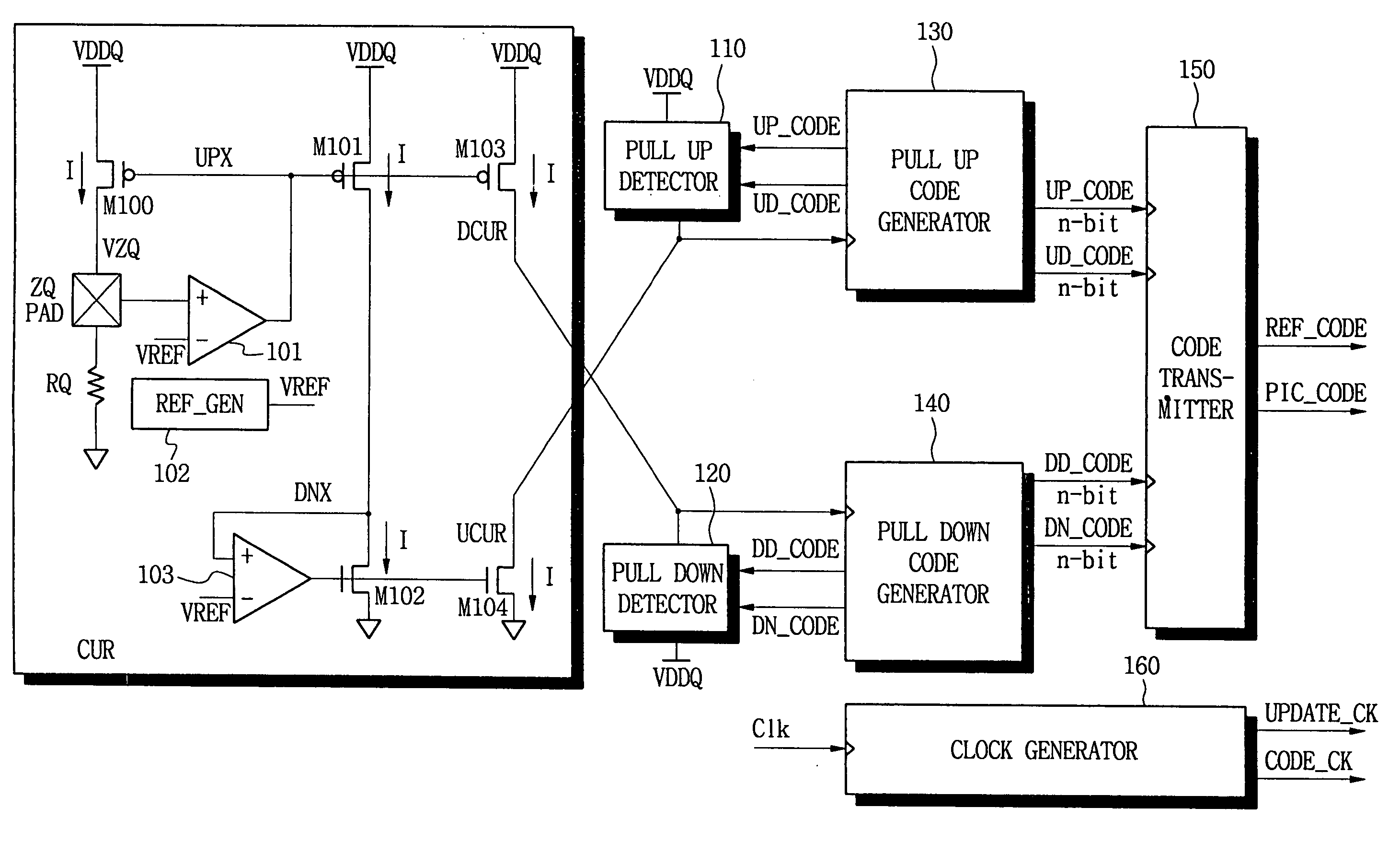
[0056]FIG. 4 illustrates a schematic block diagram of an impedance controller according to an exemplary embodiment of the invention.

[0057] Referring to FIG. 4, the impedance controller includes a current mirror section CUR for generating an impedance current I. Pull-up and pull-down detectors 110 and 120 include an array of transistors and controlled by codes that control a gate voltage or a size of the transistor array. Pull-up and pull-down code generators 130 and 140 generate codes that control the pull-up and pull-down detectors 110 and 120, respectively. And a code transmitter 150 transmits an impedance code corresponding to the impedance current. The impedance controller includes a clock generator 160 to generate a clock used for the impedance controller.

[0058] The...


PUM


Abstract

An impedance controller includes a current mirror section to generate an impedance current. At least one detector includes a transistor array and an impedance corresponding to the impedance current, the at least one detector operating responsive to a code generator. And an at least one code generator generates a first code to adjust a gate voltage of the transistor array by comparing an output of the at least one detector to a reference voltage and generates a second code to adjust a size of the transistor array by comparing the output from the at least one detector to the reference voltage.

Description

CROSS-REFERENCE TO RELATED APPLICATION [0001] This application claims priority from Korean Patent Application No. 2004-0000517, filed on Jan. 6, 2004 that we incorporate by reference.BACKGROUND [0002] 1. Technical Field [0003] The invention relates to a semiconductor device and, more particularly, to an impedance controller for impedance matching with an external device. [0004] 2. Discussion of the Related Art [0005] A variety of semiconductor devices, such as microcomputers, memory devices and the like, are used to construct a variety of electrical products. In most cases, the semiconductor devices have input / output pins for receiving and transmitting external data, an output circuit for providing internal data to external devices, and the like. A semiconductor device may provide internal data to other semiconductor devices using a transmission line. In this case, the output impedance of the input / output pins and the impedance of the transmission line must be matched to optimize si...

Claims


Application Information

Patent Timeline
Patent Type & Authority Applications(United States)
IPC IPC(8): H03H3/00H03K19/0175H03K19/003H04L25/02
CPCH03K19/00384H04L25/028H04L25/0278H03H3/00
Inventor KIM, TAE-HYOUNGKIM, NAM-SEOGCHO, UK-RAE
Owner SAMSUNG ELECTRONICS CO LTD
Why Eureka
Try Eureka