Logical operation circuit and logical operation method

a logic operation and circuit technology, applied in logic circuits characterised by logic functions, digital storage, instruments, etc., can solve problems such as the inability of the circuit to perform a logical operation on data

Inactive Publication Date: 2005-07-07
ROHM CO LTD
View PDF8 Cites 5 Cited by
  • Summary
  • Abstract
  • Description
  • Claims
  • Application Information

AI Technical Summary

Benefits of technology

[0007] A logical operation circuit according to this invention comprises: a ferroelectric capacitor having first and second terminals; first and second signal lines connected to the first and second terminals, respectively; and an output transistor. The output transistor is an electric field effect transistor which has a gate terminal connected to the first signal line and an output terminal for outputting an output signal corresponding to a control signal inputted into the gate terminal, and which becomes off when a potential on a first reference potential side from its threshold voltage is given as the control signal and becomes on when a potential on a second reference potential side from its threshold voltage is given as the control signal. In the logical operation circuit, the following operation is performed: The first and second signal lines are connected to one of the first and second reference potentials and the other of the first and second potentials, respectively, to generate a polarization state corresponding to first operation target data in the ferroelectric capacitor. The first and second signal lines are then both connected to the second reference potential to precharge the first signal line to the second reference potential without causing a change in the residual polarization state of the ferroelectric capacitor. Then, the application of voltage to the first signal line is stopped and the second signal line is connected to the first or second reference potential corresponding to second operation target data, and an output signal produced at the output terminal of the output transistor in response to a potential which is generated in the first signal line when the second signal line is connected to the first or second reference potential corresponding to the second operation target data is obtained as the result of a logical operation on the first and second operation target data.

Problems solved by technology

However, such a conventional circuit cannot perform a logical operation on data even if it can store data.

Method used


Image

  • Logical operation circuit and logical operation method
  • Logical operation circuit and logical operation method
  • Logical operation circuit and logical operation method

Examples


Embodiment Construction

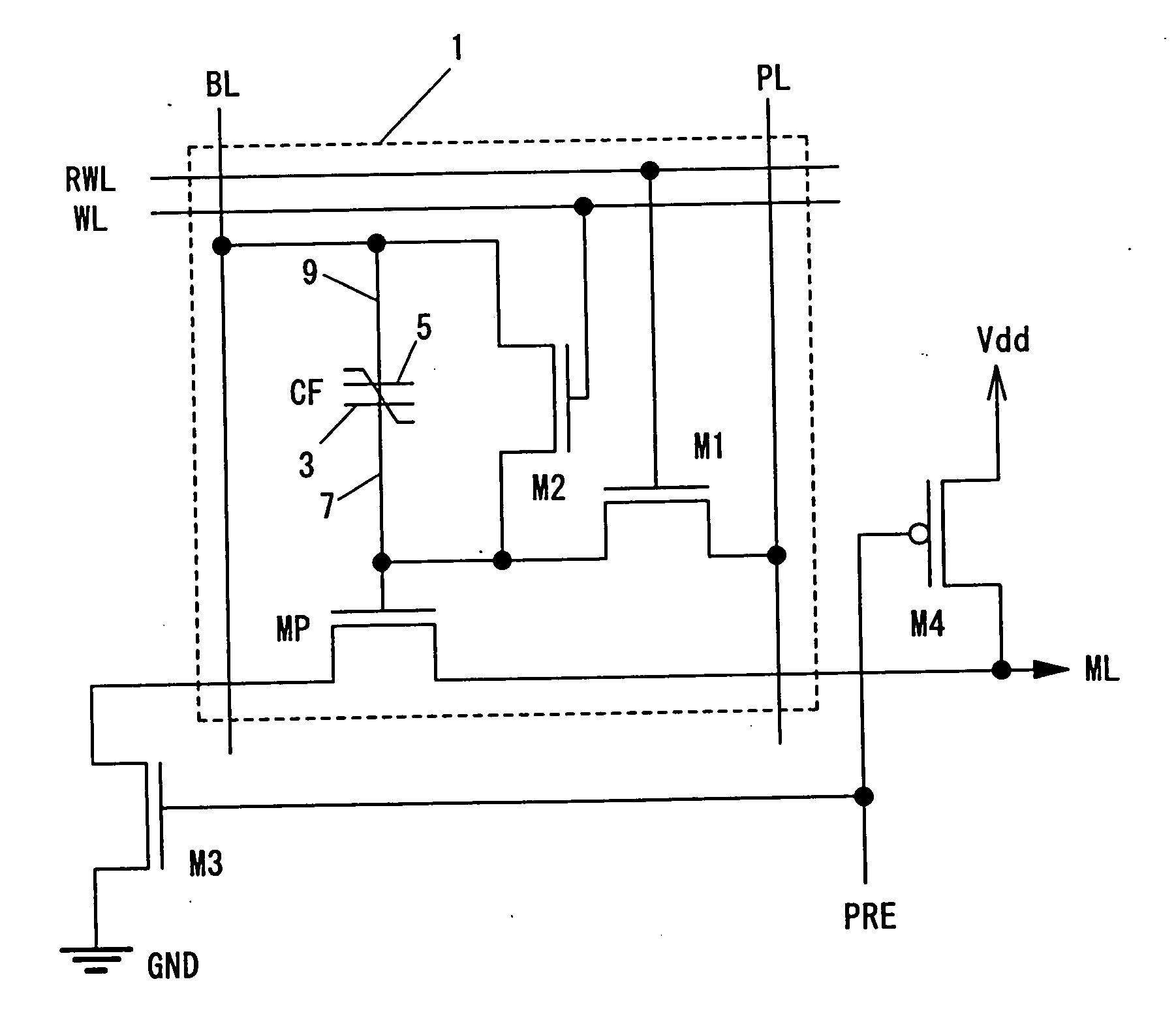
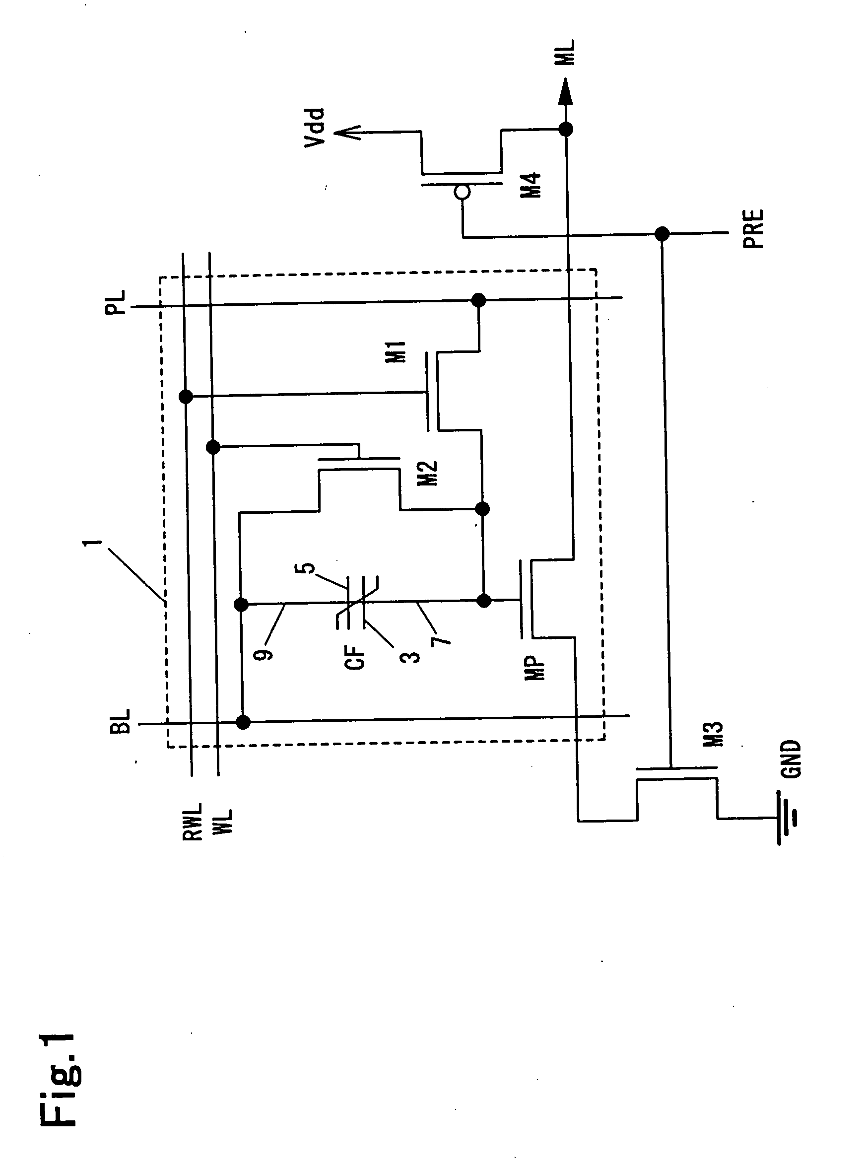
[0032]FIG. 1 is a circuit diagram illustrating a logical operation circuit 1 according to an embodiment of this invention. The logical operation circuit 1 comprises a ferroelectric capacitor CF, a transistor MP as an output transistor, and transistors M1 and M2. The transistors MP, M1 and M2 are N-channel MOSFETs (metal oxide semiconductor field effect transistors).

[0033] The ferroelectric capacitor CF has a first terminal 3 connected to a first signal line 7, and a second terminal 5 connected to a second signal line 9. The first signal line 7 is connected to a gate terminal of the transistor MP.

[0034] The first signal line 7 is connected to a plate line PL via the transistor M1 and to the second signal line 9 via the transistor M2. The transistors M1 and M2 have gate terminals connected to a read / write line RWL and a word line WL, respectively.

[0035] The transistor MP has an input terminal connected to a ground potential GND as a first reference potential via the transistor M3, ...


PUM


Abstract

To provide a logical operation circuit which can perform a logical operation using a ferroelectric capacitor and a logical operation method. A logical operation circuit 1 has a ferroelectric capacitors CF and a transistor MP. The ferroelectric capacitor CF can retain a polarization state P1 (y=1) or P2 (y=0) corresponding to first operation target data y. In an operation process, a first terminal 3 of the ferroelectric capacitor 1 is precharged to a source potential Vdd, and a potential corresponding to second operation target data x, that is, a ground potential GND (x=1) or the source potential Vdd (x=0), is given to a second terminal 5 of the ferroelectric capacitor via a bit line BL. When the threshold voltage Vth of the transistor MP is set properly, the transistor MP becomes on or off (on, on, on, off) depending on the combination of x and y (0-0, 0-1, 1-0, 1-1).

Description

CROSS-REFERENCE TO RELATED APPLICATIONS [0001] The entire disclosure of Japanese Patent Application No. 2002-18661 filed on Jan. 28, 2002 including their specification, claims, drawings and summary are incorporated herein by reference in its entirety. TECHNICAL FIELD [0002] This invention relates to a logical operation circuit and a logical operation method and, more particularly, to a logical operation circuit, a logical operation device and a logical operation method using a non-volatile memory element such as a ferroelectric capacitor. BACKGROUND ART [0003] A non-volatile memory is known as a circuit using a ferroelectric capacitor. It is possible to realize a rewritable non-volatile memory which can operate on a low voltage by using a ferroelectric capacitor. [0004] However, such a conventional circuit cannot perform a logical operation on data even if it can store data. DISCLOSURE OF THE INVENTION [0005] The object of this invention is to solve the problem of a conventional cir...

Claims


Application Information

Patent Timeline
Patent Type & Authority Applications(United States)
IPC IPC(8): G11C7/10G11C11/00G11C11/16G11C11/22G11C15/04H03K19/16H03K19/185
CPCG11C7/1006G11C11/22H03K19/185H03K19/16G11C2207/104G11C11/1659
Inventor KAMEYAMA, MICHITAKAHANYU, TAKAHIROKIMURA, HIROMITSUFUJIMORI, YOSHIKAZUNAKAMURA, TAKASHITAKASU, HIDEMI
Owner ROHM CO LTD
Why Eureka
Try Eureka