
Method of performing weighted round-robin queue scheduling using a dynamic link list and structure for implementing same

Inactive Publication Date: 2005-07-07
INTEGRATED DEVICE TECH INC
View PDF9 Cites 45 Cited by
  • Summary
  • Abstract
  • Description
  • Claims
  • Application Information

AI Technical Summary

Benefits of technology

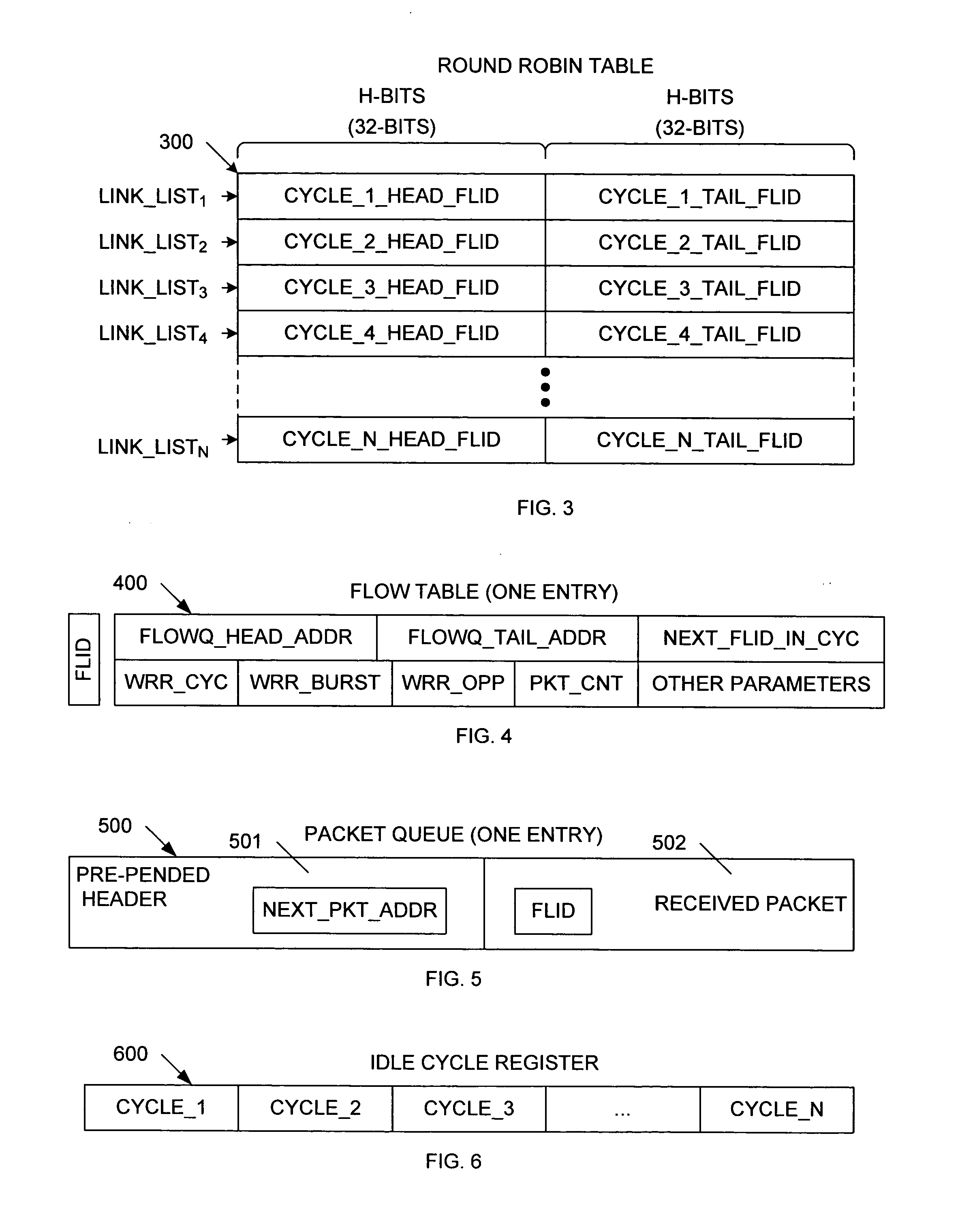
[0019] An idle cycle register is provided in accordance with one embodiment of the present invention. The idle cycle register includes a 1-bit idle cycle indicator for each cycle. If a cycle link list is linked to at least one flow table entry (i.e., at least one packet waiting to be dequeued), then the associated idle cycle indicator is de-activated, thereby indicating that the cycle link list is active (not idle). Conversely, if a cycle link list is linked to no flow table entries, then the associated idle cycle indicator is activated, thereby indicating that the cycle link list is idle. The WRR scheduler only processes active cycle link lists, thereby improving processing speed (i.e., packet throughput).

Problems solved by technology

The drawback of the FIFO scheme is that bandwidth is not distributed fairly among all of the traffic flows.
However, round-robin scheduling has two problems.
The first problem is that this scheme cannot differentiate large packets from small packets.
Although this method is efficient at processing backlogged queues, it has the negative effect of forwarding the packets from each flow in a clumped manner (e.g., 10 packets at a time) rather than a smooth manner (e.g., 1 packet at a time).
The real problem with the above-described weighted round-robin scheduling is that it fails to work properly when the network is not heavily loaded.

Method used


Image

  • Method of performing weighted round-robin queue scheduling using a dynamic link list and structure for implementing same
  • Method of performing weighted round-robin queue scheduling using a dynamic link list and structure for implementing same
  • Method of performing weighted round-robin queue scheduling using a dynamic link list and structure for implementing same

Examples


Embodiment Construction

[0035] The present invention provides an improved method for implementing weighted round-robin (WRR) scheduling. In accordance with one embodiment of the present invention, a dynamic queue link list is used to implement an improved weighted round-robin scheduling technique.

[0036] Before further describing the weighted round-robin (WRR) technique of the present invention, the terms “flow table” and “flow identification” (or FLID), shall be introduced. A flow table contains the parameters necessary for processing received data packets. The flow table entries (e.g., assigned bandwidth) are stored in either an external or internal memory block called the flow table memory. Each flow has a corresponding flow table entry in the flow table memory.

[0037] A flow identification (FLID) value is used to identify each individual packet flow. The FLID value is defined as an H-bit field, where H is a given integer. In the described example, H is equal to 32, although this is not necessary. The F...


PUM


Abstract

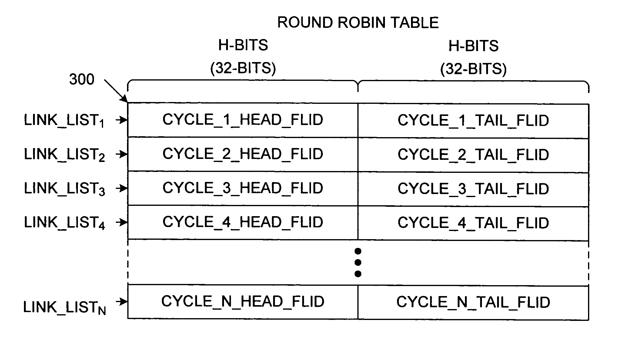
A weighted round-robin scheduler includes a round-robin table that stores a plurality of cycle link lists. Each cycle link list includes a head flow identification (FLID) value identifying a first flow of the cycle link list, and a tail FLID value identifying a last flow of the cycle link list. A flow table is provided having a plurality of flow table entries. Each flow table entry is associated with a corresponding flow. Each flow table entry stores a parameter that identifies the weight assigned to the associated flow. A packet queue is associated with each flow table entry, wherein each packet queue is capable of storing a plurality of packets. The weighted round-robin scheduler also includes an idle cycle register having an idle cycle entry corresponding with each of the cycle link lists, wherein each idle cycle entry identifies the corresponding cycle link list as active or idle.

Description

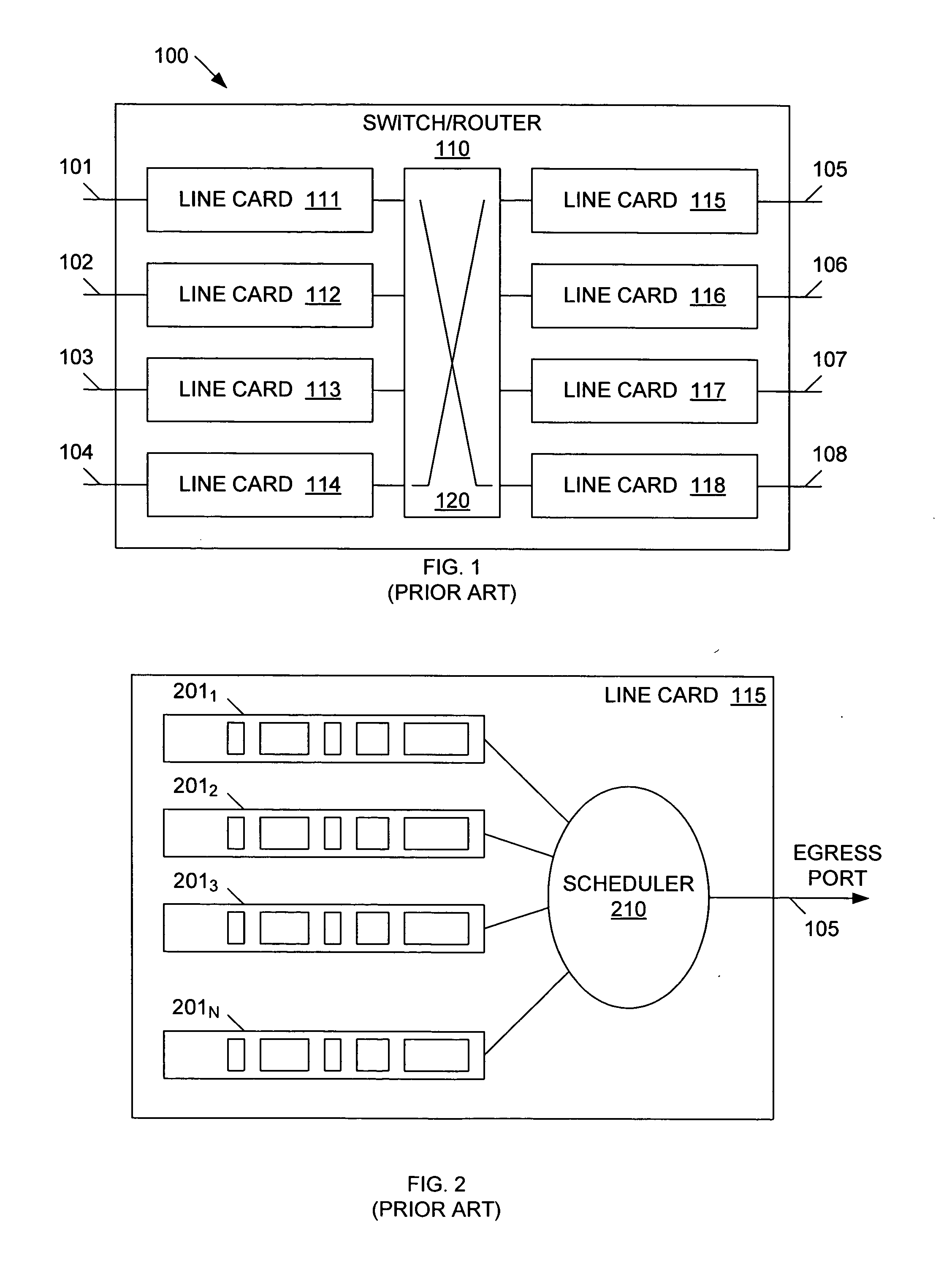
RELATED APPLICATION [0001] The present application is based on and claims priority of U.S. provisional Patent Application Ser. No. 60 / 497,883 filed by Yongdong Zhao and Craig A. Lindahl on Aug. 25, 2003.BACKGROUND OF THE INVENTION [0002] 1. Field of the Invention [0003] The present invention relates to an improved queuing method for implementing weighted round-robin (WRR) scheduling for high-speed packet switching and routing. [0004] 2. Related Art [0005] Queuing and scheduling are two critical function blocks that are used by today's packet switches and routers to support quality of services (QoS). A typical packet switch / router has multiple ports forwarding and receiving data packets. Usually a data packet enters a switch / router from one port and departs from another port. The switch / router ports can each receive and forward data packet simultaneously. [0006]FIG. 1 is a block diagram of a high-level switch / router architecture 100 that includes switch ports 101-108 and switch / route...

Claims


Application Information

Patent Timeline
IPC IPC(8): H04L1/00H04L12/56
CPCH04L12/5693H04L47/623H04L47/6225H04L47/50
Inventor ZHAO, YONGDONGLINDAHL, CRAIG A.
Owner INTEGRATED DEVICE TECH INC
Learn More