Dental implant fixture

a technology for dental implants and fixtures, applied in bridge construction, medical science, construction, etc., can solve the problems of high fabrication and maintenance costs, hygiene problems, and patients' high costs

Inactive Publication Date: 2005-07-07
NORTHERN ENG IND PLC +1
View PDF22 Cites 30 Cited by
  • Summary
  • Abstract
  • Description
  • Claims
  • Application Information

AI Technical Summary

Benefits of technology

[0021] Accordingly, it is a general object of the present invention to provide an improved fixture such that many of the problems related to implant placement are eliminated.

Problems solved by technology

The screw-type dental implant system needs a lot of parts, so that a fabrication and maintenance cost are high.
In addition, since implant surgical operation is complicated, complication arises and the patients may pay a lot of costs.
An attachment features between the fixture and the abutment may have a problem, so that a certain gap is formed therein.
Since bacteria may be infected through the gap, a hygiene problem may occur.
In addition, inflammation may occur in the infected portions, so that alveolar bone may be damaged.
But since the type is not-screw type, it is difficult to insert and disengage the fixture at implant surgical operation.
Therefore, the engagement and disengagement works are complicated.
As shown in FIG. 1, since the conventional fixture does not have wrench groove, an operation work of the fixture is not easy.

Method used


Image

  • Dental implant fixture
  • Dental implant fixture
  • Dental implant fixture

Examples


Embodiment Construction

[0033] The present invention will now be described more fully hereinafter with reference to the accompanying drawings, in which preferred embodiments of the invention are shown.

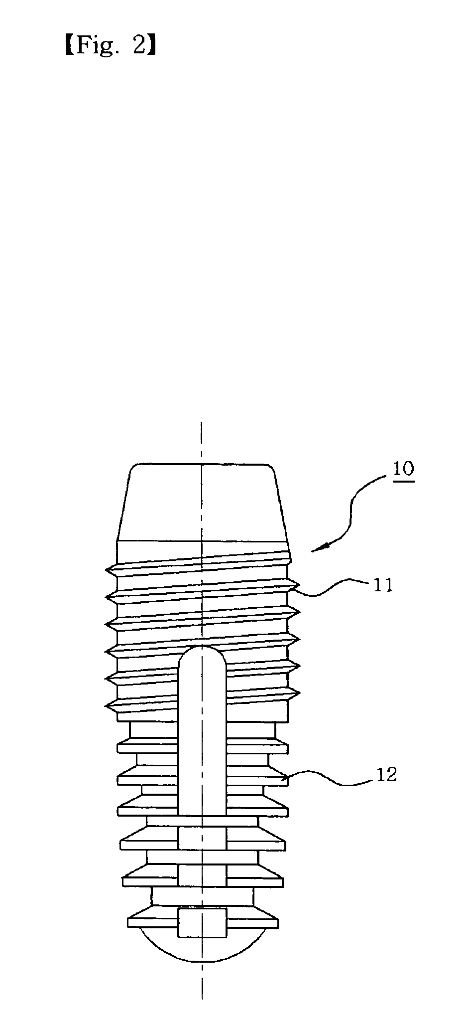
[0034]FIG. 2 is a front view of a fixture, FIG. 3 is a cross sectional view of the fixture, FIG. 4 and FIG. 5 respectively are a plant view and a cross sectional view of the preferred embodiment of a fixture of the present invention.

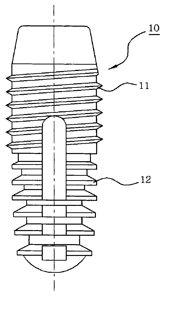
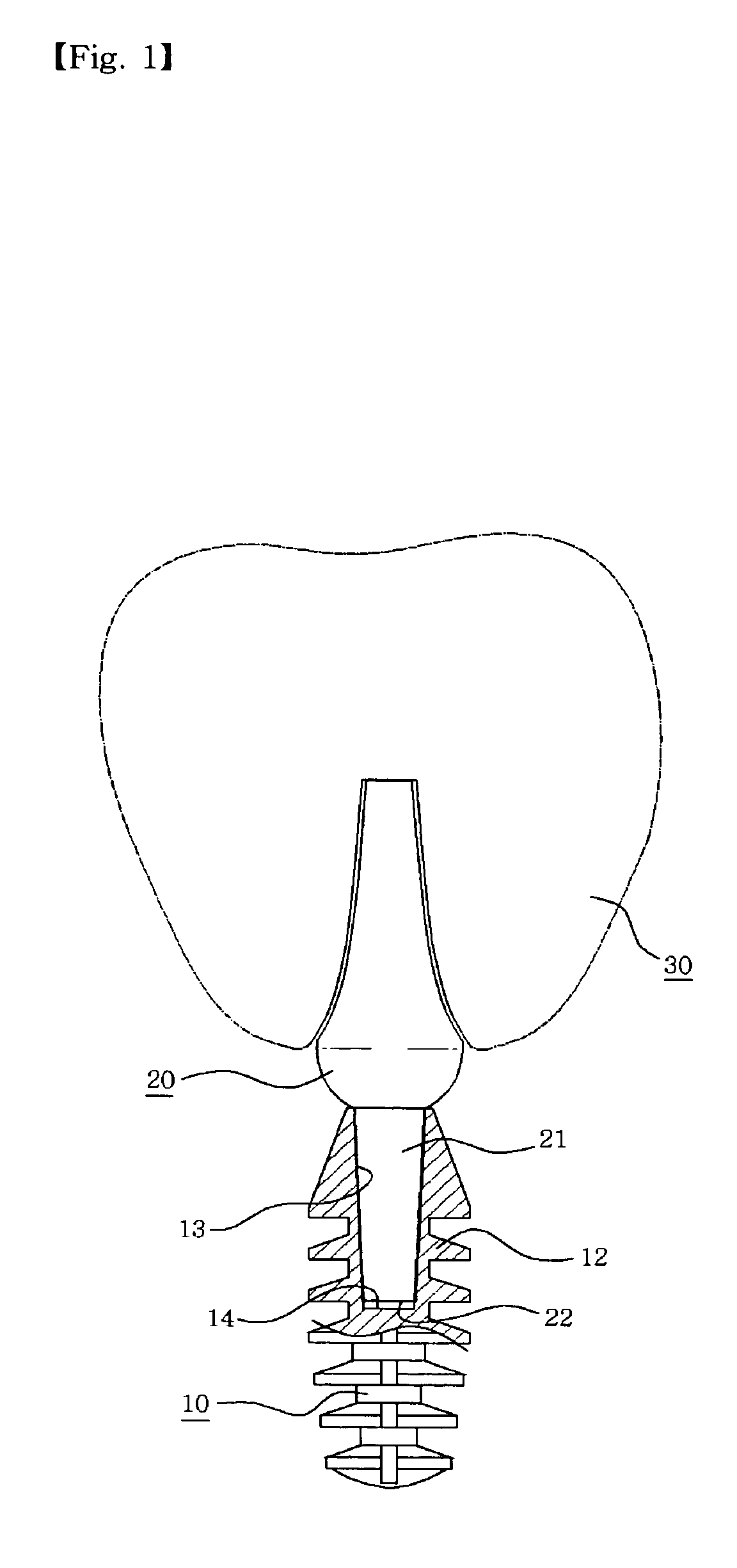
[0035] The dental implant system includes a fixture 10 having a tapered hole 13 on a cylindrical upper surface, an abutment 20 that has a taper post portion 21 inserted into the hole 13 of the fixture, and a crown 30 that is assembled to an upper side of the abutment.

[0036] With reference now to FIG. 2, the fixture 10 has a threaded portion 11 formed in an upper external cylindrical surface and a plurality of circular plate pins 12 formed in a lower external cylindrical surface.

[0037] In addition, the threaded portion 11 is provided for achieving an easier engagement and disen...


PUM


Abstract

The present invention relates to dental implant fixture capable of achieving an easier engagement and disengagement operations using a screw by forming a threaded portion and a circular plate pin portion in an external cylindrical surface of an fixture and preventing a screw from being loosened by using a circular plate pin, thereby achieving a stable placement and easier implant surgical operation. The improved dental implant fixture comprises a threaded portion formed in an upper external cylindrical surface of the fixture for achieving an easier and convenient engagement and disengagement; and a plurality of circular plate pins provided in a lower external cylindrical surface for enhancing a stability when an alveolar bone is grown, wherein the hole has a deeper space at a bottom end for preventing an air compression problem when the post portion of the abutment is assembled.

Description

BACKGROUND OF THE INVENTION [0001] 1. Field of the Invention [0002] The present invention relates to a dental implant fixture. More particularly, the present invention relates to an improved fixture of a tapered locking type having a threaded portion and a circular plate pin portion in an external cylindrical surface. And a deeper space is additionally formed in an inner bottom of a hole into which a post portion of an abutment is inserted, thereby preventing a loosening due to compressed air. In addition the deeper space is formed in a wrench groove, thereby achieving an easier implant surgical operation. [0003] 2. Description of the Background Art [0004] Dental implant system is that an abutment is attached to a fixture inserted into an alveolar bone and a crown covers the abutment. Each implant is independently anchored, and the anchored implant does not rely on neighboring teeth for support. Therefore, it is not needed to damage natural teeth for supporting the damaged tooth. Ac...

Claims


Application Information

Patent Timeline
Patent Type & Authority Applications(United States)
IPC IPC(8): A61C8/00
CPCA61C8/0018A61C8/0071A61C8/0022E01D19/02E01D21/00
Inventor CHANG, SANG-KOHN
Owner NORTHERN ENG IND PLC
Why Eureka
Try Eureka