Heat sink and method for manufacturing the same

a technology of heat sink and heat sink, which is applied in the direction of lighting and heating apparatus, semiconductor devices, and semiconductor/solid-state device details. it can solve the problems of inability to significantly reduce the weight of the conventional heat sink b>1/b>, time-consuming and expensive connection of the plate-like base, and achieve the effect of convenient manufacturing and high heat dissipation efficiency

Inactive Publication Date: 2005-07-14
THERMAL TECH
View PDF3 Cites 10 Cited by
  • Summary
  • Abstract
  • Description
  • Claims
  • Application Information

AI Technical Summary

Benefits of technology

[0010] It is an object of the present invention to provide a heat sink and a method for manufacturing a heat sink that is easily manufactured, cheap and highly efficient in heat dissipation.
[0011] It is another object of the present invention to provide a method for manufacturing a heat sink made of different materials and that is lighter and highly efficient in heat dissipation.
[0012] It is another object of the present invention to provide a heat sink made of different materials and that is lighter and highly efficient in heat dissipation.

Problems solved by technology

No matter what the plate-like base 11 and a plurality of fins 12 are made of, it is time-consuming and expensive to connect the plate-like base 11 and a plurality of fins 12 by soldering.
Although the conventional heat sink 1 is made of lightweight aluminum instead of the heavier copper, the weight of the conventional heat sink 1 cannot be decreased.
However, the fins 12 are soldered to most of the area of the plate-like base 11 so that the weight of the conventional heat sink 1 fails to be significantly decreased.

Method used


Image

  • Heat sink and method for manufacturing the same
  • Heat sink and method for manufacturing the same
  • Heat sink and method for manufacturing the same

Examples


Embodiment Construction

[0022] The following detailed description is of the best presently contemplated modes of carrying out the invention. This description is not to be taken in a limiting sense, but is made merely for the purpose of illustrating general principles of embodiments of the invention. The scope of the invention is best defined by the appended claims.

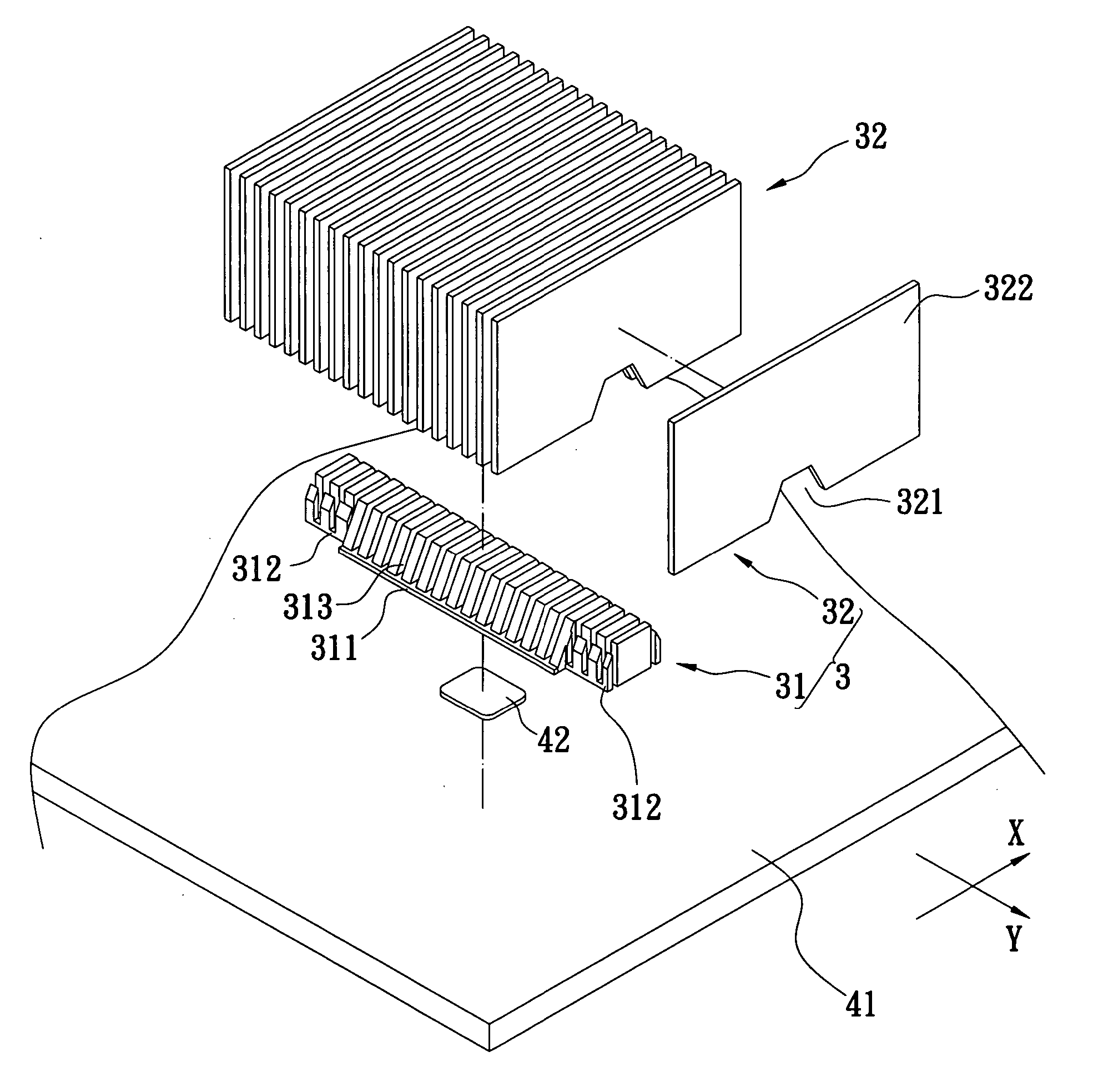
[0023]FIGS. 3-5 illustrate a heat sink 3 in accordance with one embodiment of the present invention. The heat sink 3 has a plate-like base 31 and a plurality of fins 32 positioned on the plate-like base 31. The plate-like base 31 has a central segment 311 and two flange segments 312. The two flange segments 312 correspond to and extend from both ends of the central segment 311 in the direction of arrow Y. The central segment 311 and the two flange segments 312 have their corresponding top surfaces and bottom surfaces. The top surfaces of the central segment 311 and the two flange segments 312 are in the same plane, and the bottom surfaces of the...


PUM


Abstract

A heat sink and a method for manufacturing a heat sink are described. A plate-like base is manufactured with a plurality of parallel grooves and a plurality of fins by an impact extrusion process. A high temperature heat treatment is performed to soften the plate-like base. The fins are positioned in corresponding grooves and an equal force is applied to both ends of the plate-like base so that the grooves are deformed and the fins are fixedly positioned. The method is simpler and significantly cheaper than that for conventional heat sinks.

Description

BACKGROUND OF THE INVENTION [0001] 1. Field of the Invention [0002] The present invention relates to a heat sink and a method for manufacturing the same, and in particular to a heat sink and a method for manufacturing a heat sink that is easily manufactured, cheap and highly efficient in heat dissipation. [0003] 2. Description of Related Art [0004] Referring to FIGS. 1 and 2, a conventional heat sink 1 is disclosed. The conventional heat sink 1 has a plate-like base 11 and a plurality of fins 12. The plate-like base 11 and plurality of fins 12 are manufactured by an impact extrusion process and can be made of copper. Then, thermal transfer adhesive is applied to the bottom of the fins 12 which are equidistantly separated and positioned on top surface of the plate-like base 11. [0005] In addition, the plate-like base 11 and plurality of fins 12 can also be made of copper and aluminum, respectively. Compared with the heat sink made of copper in the prior art, the heat sink described a...

Claims


Application Information

Patent Timeline
Patent Type & Authority Applications(United States)
IPC IPC(8): F28F13/00H01L21/48H01L23/367
CPCF28F13/00H01L21/4882H01L23/3672H01L2924/0002H01L2924/00
Inventor LEE, TZUNG-LUNGLIN, MING-CHEN
Owner THERMAL TECH
Why Eureka
Try Eureka