Protective case for information storage disc

a protective case and information storage technology, applied in the field of protective cases, to achieve the effect of increasing structural strength, facilitating opening the case, and reducing mechanical damag

Inactive Publication Date: 2005-07-14
OSBORN WARREN R +1
View PDF10 Cites 7 Cited by
  • Summary
  • Abstract
  • Description
  • Claims
  • Application Information

AI Technical Summary

Benefits of technology

[0011] The present invention has for its object the provision of an improved, three-piece protective jewel case for disc-shaped information storage media. The case, which is of the clam-shell type, is preferably injection molded from optically transparent polymeric plastic material, and includes a base member having a pair of generally rectangular hinge alcoves positioned at adjacent corners along a rear side edge thereof, a lid member having a pair of generally rectangular hinge arms positioned at adjacent corners along a rear side edge thereof, and a media tray which snaps into the base member. For a preferred embodiment of the case, the media tray is hingeably connected to the base member along the rear side edge. The hinge arms differ from those of the '590 patent in that, rather than being a vertical rectangular tube closed at one end, each hinge arm has a rectangular solid component in the pivot plane that extends from the outer edge to the inner edge and from the front edge to the back edge thereof. This feature rigidifies the rectangular hinge so that it is much more resistant to mechanical damage from crushing or dropping loads. Other significant features of the improved storage case are thicker walls; stronger corners; a hub and outer ring on the media tray having heights sufficient to support the lid when the latter is subjected to crushing loads; multiple, spaced-apart posts on the spine of the media tray, which support the rear edge of the lid member; double, spaced-apart, positive locking tabs positioned along the front edge of the case; a wide finger opening between the lid member and the base member, which facilitates opening the case; a base member which nests inside the lid member; a thick ridge around the edges of the case for increased structural strength; clear edges for an unobstructed view of graphic inserts; and at least a pair of finger recesses on the ring of the media tray to facilitate removal of a stored disc.
[0012] A preferred embodiment of the housing according to the invention has the characteristic that for each corner hinge either the hinge arm or the hinge wall is provided with a stud which projects into a circular opening in the associated mating hinge component. The hinge arms and the hinge alcoves are thus hingeably coupled to one another as is well known in the prior art of jewel cases. To facilitate the fastening of the lid member to the base member, the hinge arms are preferably resilient in directions that permit them to be pulled apart from one another a distance sufficient for the studs of the lid member to engage the openings in the base member, without fracturing the lid member. After assembly, the resilient hinge arms return to their original position, thereby ensuring that the studs remain locked in the openings. Alternatively, the base member can be temporarily distorted to narrow the distance between the openings, or both components may be temporarily distorted to lessen the assembly stresses on a single component. The media tray is coupled to the base member in a like manner using pivots and mating openings.
[0013] Three configurations of media trays or base member inserts are contemplated by the present invention. All three configurations, or embodiments, preferably incorporate multiple posts along a rear stiffening rib that help support the rear edge of the lid member. The first configuration is a partial media tray, which includes a disc mounting region, a hub to secure the center of the disc, and sufficient appendages to secure it to the base member. The second is a full media tray which covers essentially the entire area of the base member. The third is simply a rib, which provides rigidity to the base member and helps support the rear edge of the lid member.
[0014] The polymeric plastic material from which the case is injection molded is selected preferably from the group consisting of polystyrene, styrene acrilonitrile, or polycarbonate, with polystyrene being the weakest and least expensive of the three materials, and polycarbonate being the most expensive (currently about double the cost of polystyrene) and strongest of the three. When low cost and reasonable strength are both significant product factors, styrene acrilonitrile is good choice. Currently, the material costs less than ten percent more than polystyrene. Protective jewel cases made from styrene acrilonitrile in accordance with the present invention have sufficient impact resistance to be mailed without external packaging. Although it is assumed that a small percentage of the cases will be damaged in the mailing process, it is believed that an overwhelming great majority will arrive at their destination without damage.

Problems solved by technology

Although it is assumed that a small percentage of the cases will be damaged in the mailing process, it is believed that an overwhelming great majority will arrive at their destination without damage.

Method used


Image

  • Protective case for information storage disc
  • Protective case for information storage disc
  • Protective case for information storage disc

Examples


first embodiment

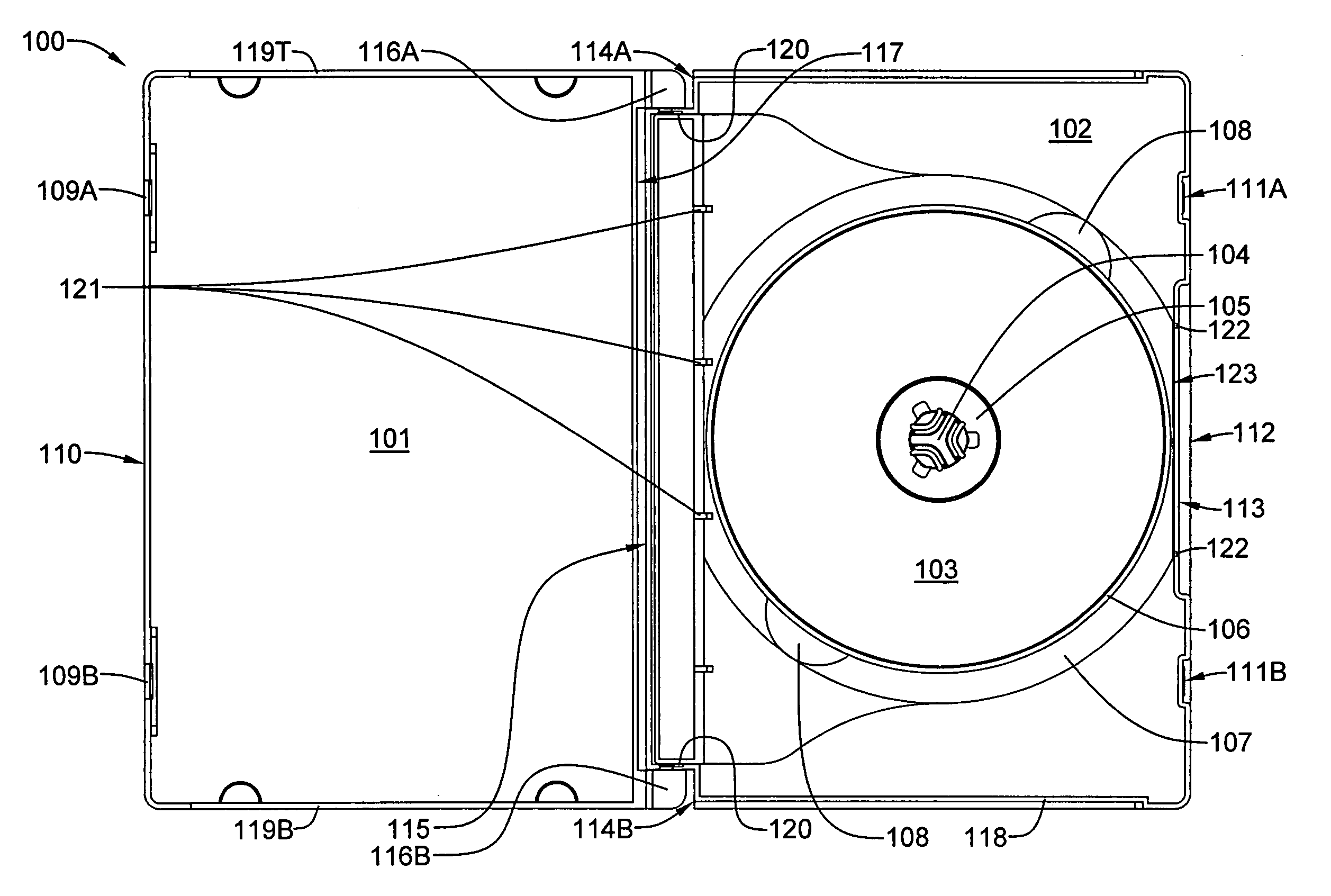
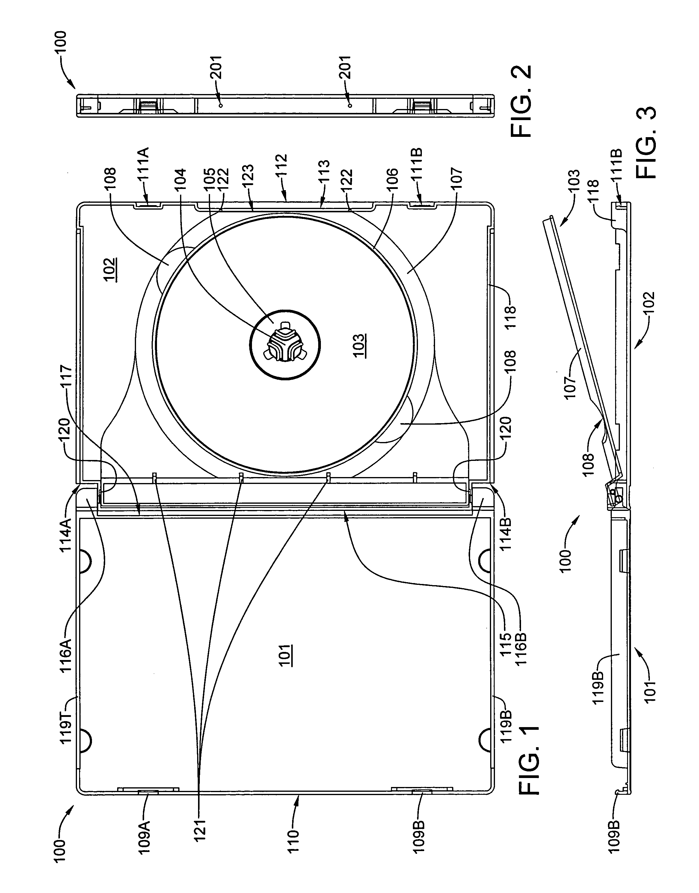
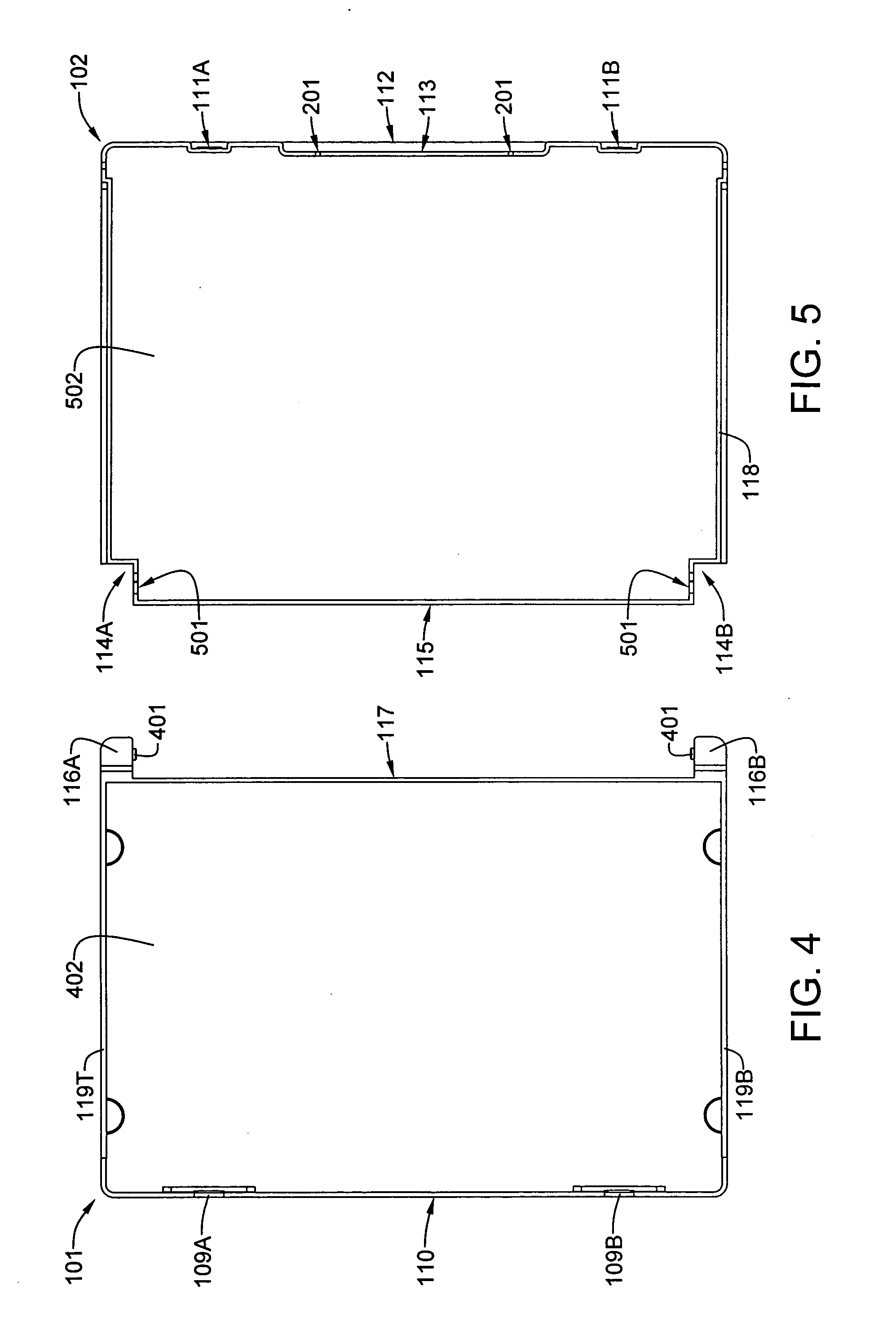
[0041] Still referring to FIG. 1, it will be noted that the base member 101 incorporates a pair of hinge alcoves 114A and 114B, which are located at opposite ends of the rear edge 115 of the base member 102. It will also be noted that the lid member 101 incorporates a pair of hinge arms 116A and 116B located at opposite, adjacent corners on the rear edge 117 of the lid member 101. The lid member 101 and the base member 102 are hingeably coupled via a system of axially-aligned studs and apertures. For the preferred embodiment, each of the hinge alcoves 114A and 114B incorporates a cylindrical aperture that is axially aligned with the cylindrical aperture of the other hinge alcove. Each of the hinge arms 116A and 116B incorporates a pivot stud that is axially aligned with the pivot stud of the other hinge arm. By slightly distorting the lid member 101, the base member 102, or both, the lid member 101 can be pivotally attached to the base member 102. It will be further noted that the b...

second embodiment

[0050] Referring now to FIGS. 11 and 12, the hinge arm 117A of FIGS. 9 and 10 has been modified to remove additional polymeric plastic material by forming dimples in the upper and lower surfaces thereof. The modified second embodiment hinge arm 1101A is still solid from side to side through the pivot axis 1103.

[0051] Referring now to FIGS. 13 and 14, a third embodiment hinge arm 1301A retains the full height H2 of the jewel case. However, polymeric plastic material has been removed in the well 1302 shown in FIG. 13 and in the valley 1401 shown in FIG. 14. Nevertheless, the third embodiment hinge arm 1301A is still solid from side to side through the pivot axis 1103.

[0052] Referring now to FIG. 15 and 16, a second embodiment media tray 1501 completely covers the inner surface of base member 102. This may be an advantageous feature when a paper base member insert or label is used, as media tray 1501 will completely cover a full-size insert. Other than size, the primary difference bet...


PUM


Abstract

A three-piece jewel case for information storage discs, such as CDs and DVDs, is of the clam-shell type, and includes a base portion having a pair of generally rectangular hinge recesses positioned at adjacent corners along a rear side edge thereof, a lid portion having a pair of generally rectangular hinge arms positioned at adjacent corners along a rear side edge thereof, and a media tray having a lid portion supporting hub, which snaps into the base portion. For a preferred embodiment of the case, the media tray is hingeably connected to the base portion along the rear side edge. Each hinge arm has a rectangular solid component that extends from the outer edge to the inner edge and from the front edge to the back edge thereof. This feature rigidifies the rectangular hinge so that it is much more resistant to mechanical damage from crushing or dropping loads.

Description

BACKGROUND OF THE INVENTION [0001] 1. Field of the Invention [0002] The invention relates generally to protective cases for storing and shipping disc-shaped information storage media such as compact discs and digital video disks and, more particularly to protective jewel cases of a clam-shell design comprising an assembly of three pieces: a bottom cover piece, a top cover piece hingeably connected to the bottom cover piece, and an internal swing-out piece hingeably connected to the bottom cover piece. [0003] 2. History of the Prior Art [0004] The use of optically-scannable discs for high-density storage of digital data has exploded since the advent of the compact disc (CD) in 1983. Capable of storing 650 to 700 megabytes of digital data, a single CD could hold 74 to 80 minutes of high-quality music. Fourteen years later, the digital video disc (DVD) was introduced. Although a DVD is identical in thickness (1.2 millimeters) and diameter (120 millimeters or 4.7 inches) to a standard C...

Claims


Application Information

Patent Timeline
Patent Type & Authority Applications(United States)
IPC IPC(8): B65D85/57
CPCG11B33/0427
Inventor OSBORN, WARREN R.DUNFORD, BRYAN P.
Owner OSBORN WARREN R
Why Eureka
Try Eureka