Thermal interface material (TIM) with carbon nanotubes (CNT) and low thermal impedance

a technology of thermal interface material and carbon nanotube, applied in the field of thermal interface material (tim) with low thermal impedance, can solve the problems of many limitations

Inactive Publication Date: 2005-07-14
UNIV OF WASHINGTON
View PDF2 Cites 48 Cited by
  • Summary
  • Abstract
  • Description
  • Claims
  • Application Information

AI Technical Summary

Problems solved by technology

There are two technical issues associated with the above thermal management.
One issue is how to design a thermal interface material (TIM) that transports high heat flux emitting from the microprocessor or pumped laser diode chip effectively and promptly.
The second issue is how to ensure measurements of thermal properties of a thermal interface material are accurate.
There are several thermal interface materials that meet this challenge, but many still have limitations.

Method used


Image

  • Thermal interface material (TIM) with carbon nanotubes (CNT) and low thermal impedance
  • Thermal interface material (TIM) with carbon nanotubes (CNT) and low thermal impedance
  • Thermal interface material (TIM) with carbon nanotubes (CNT) and low thermal impedance

Examples


Embodiment Construction

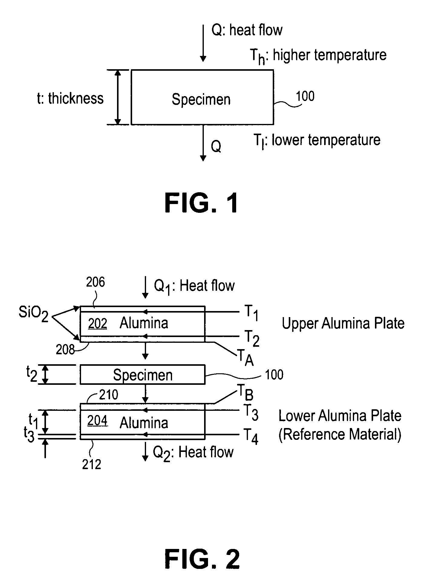
[0025]FIG. 1 is a schematic diagram illustrating a thermal interface material 100 (specimen) according to an embodiment of the present invention. The thermal interface material 100 includes a thickness (t), a high temperature (Th), a low temperature (Tl), and a heat flow (Q).

[0026] One-dimensional heat conduction under steady-state condition is given by: QA=K⁢Δ⁢ ⁢TΔ⁢ ⁢x(1)

where Q is the heat flow in watts, A, Δx and K are surface area, thickness and thermal conductivity of the thermal interface material 100, respectively, and ΔT is temperature difference between high temperature (Th) and low temperature (Tl).

[0027] Thermal resistance R (K / W) is defined from equation (1). R=Δ⁢ ⁢TQ=Th-T1Q=tKA(2)

[0028] Sometimes, thermal impedance θ (Kcm2 / W) is a convenient property that is defined as: θ=RA=tK(3)

[0029]FIG. 2 is a schematic diagram illustrating an apparatus 200 fabricated according to embodiments of the present invention. In the illustrated embodiment, the thermal interface materi...


PUM

PropertyMeasurementUnit
thicknessaaaaaaaaaa
thicknessaaaaaaaaaa
weightaaaaaaaaaa

Abstract

According to embodiments of the present invention, a very thin thermal interface material (TIM) is developed, which is composed of carbon nanotubes, silicon thermal grease, and chloroform. The carbon nanotubes and chloroform comprise the filler and the silicone thermal grease comprises the matrix.

Description

CROSS REFERENCE TO RELATED APPLICATIONS [0001] This application claims the benefit of U.S. Provisional Application No. 60 / 528,979, filed Dec. 12, 2003.BACKGROUND [0002] 1. Field [0003] Embodiments of the present invention relate to packaging of electronic components and, in particular, to thermal interface material (TIM) for use with electronic components. [0004] 2. Discussion of Related Art [0005] Thermal management is a key task for an electronic packaging engineer working on high power integrated circuits such as microprocessors and pumped laser diodes, for example. There are two technical issues associated with the above thermal management. One issue is how to design a thermal interface material (TIM) that transports high heat flux emitting from the microprocessor or pumped laser diode chip effectively and promptly. The second issue is how to ensure measurements of thermal properties of a thermal interface material are accurate. [0006] A goal of development of new thermal interf...

Claims


Application Information

Patent Timeline
Patent Type & Authority Applications(United States)
IPC IPC(8): G01K1/16
CPCB82Y10/00B82Y30/00G01K1/16H05B2214/04Y10S977/787Y10S977/786Y10S977/955Y10S977/785Y10S977/778
Inventor TAYA, MINORUPARK, JONG-JIN
Owner UNIV OF WASHINGTON
Why Eureka
Try Eureka