
Composite Heat Sink For Electrical Components

a heat sink and electrical component technology, applied in semiconductor devices, light sources, light-emitting devices, etc., can solve the problems of limiting the range of metals, limiting the heat conduction range, and reducing the thermal performance of metal core printed circuit boards. achieve the effect of strong mechanical connection

Inactive Publication Date: 2015-09-17
BRETSCHNEIDER ERIC COLIN
View PDF0 Cites 17 Cited by
  • Summary
  • Abstract
  • Description
  • Claims
  • Application Information

AI Technical Summary

Benefits of technology

The patent text describes a way to connect a printed circuit board and a heat sink with strong screws or clips. This allows for better heat transfer and can also isolate the LEDs from the environment. The technical effect is improved performance and reliability of the heat sink and printed circuit board assembly.

Problems solved by technology

Heat conduction is still limited because of the low cross sectional area of metal in the thermal vias.
Unfortunately the better thermal performance of metal core printed circuit boards comes at a significant price premium.
The processing conditions for dielectric materials and electrical traces also limits the range of metal allows that may be used for the metal core.
This limits efforts at price reduction.
Other metals and alloys are not used due to their incompatibility with the printed circuit forming process.
There is a limit to the thickness of metal that can be used in metal core printed circuit boards.
This limit is imposed by the processing steps used to form metal core printed circuit boards.
This limits the ability of this surface to act as an effective heat transfer component.
This contradictory situation is forced upon users by the processing steps required to form a metal core printed circuit board.
While the cost of thermal vias to a standard FR4 type printed circuit board is much less than a metal core printed circuit board, the heat transfer performance is still much lower than metal core printed circuit boards.
This flexibility may severely comprise the ability to mount the printed circuit board to a heat sink without introducing detrimental air pockets and voids.
If such a device is mounted so that the LED side of the printed circuit board is oriented in a vertical direction, the effectiveness of convective heat transfer is severely reduced.
It is also difficult in such devices to secure optics as a mechanical attachments must extend through the printed circuit board to the surface from which the protrusions extend.
Additional features and components may be used to secure optics, but these add cost and complexity.
Printed circuit boards lack the mechanical strength to allow simple installation of optical components which can form a seal around the LEDs and isolate them from the environment.

Method used


Image

  • Composite Heat Sink For Electrical Components
  • Composite Heat Sink For Electrical Components
  • Composite Heat Sink For Electrical Components

Examples


Embodiment Construction

[0020]Printed circuit boards are commonly made using rigid composite materials such as FR4 or CEM. These materials have excellent electrical insulating and dielectric properties. They are also physically strong and rigid and have excellent flame resistance. The term FR4 derives from Flame Retardant type 4. They are also inexpensive.

[0021]This host of attractive features and properties is balanced against a significant weakness-low thermal conductivity. FR4 has a through plane thermal conductivity of about 0.29 W / m° K. This stands in stark contrast to aluminum alloys commonly used to produce aluminum core printed circuit boards. These aluminum alloys have thermal conductivities that range from about 100 W / m° K to about 180 W / m° K. This makes these materials about 300 to about 600 times better thermal conductors.

[0022]The units of thermal conductivity are W / m° K. Knowing this, the thermal resistance across a given thickness of material can be calculated by multiplying the thermal cond...


PUM


Abstract

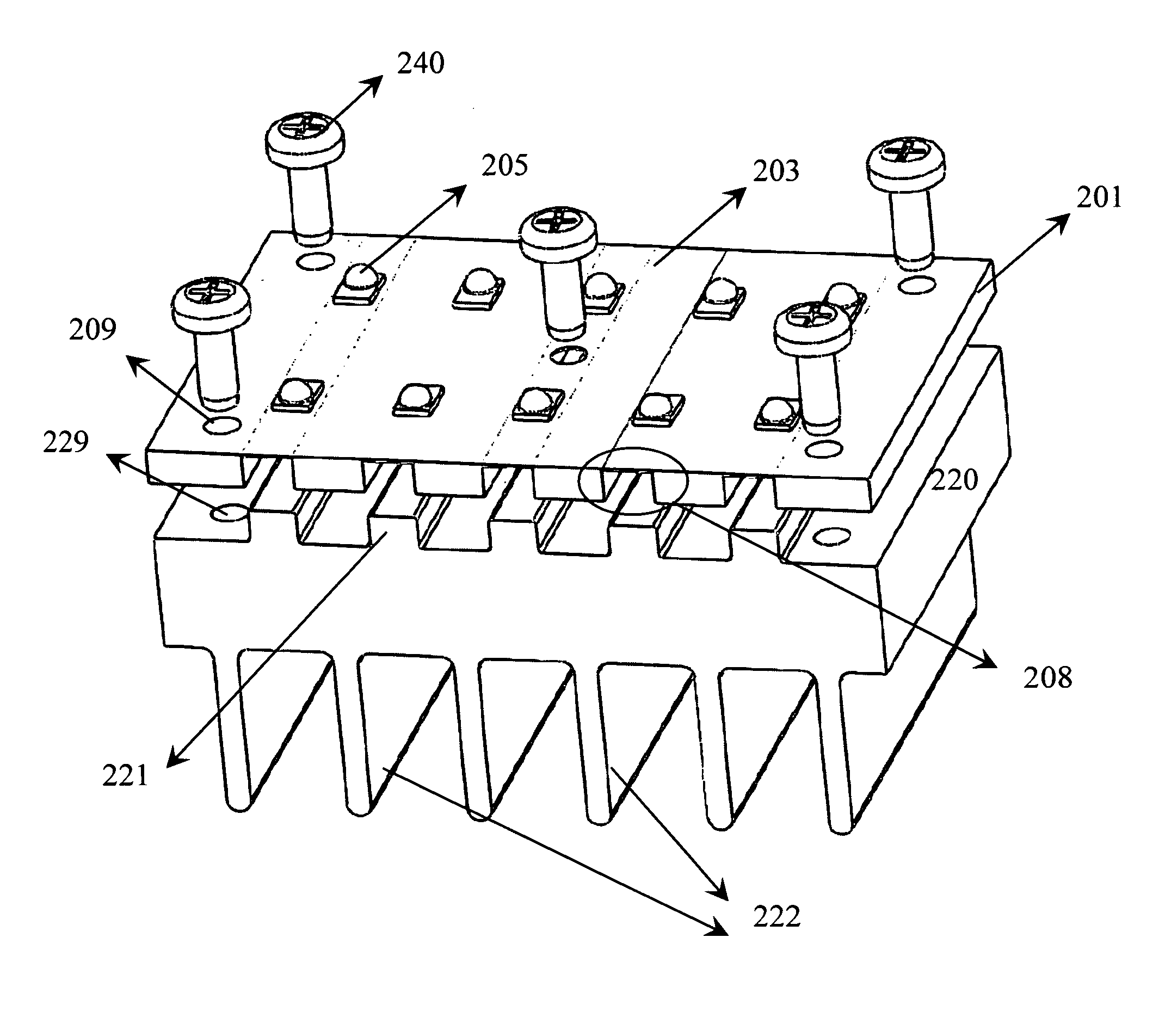
A composite heat sink with improved mechanical strength and thermal conductivity can be made using a printed circuit board with machined recesses on the back side. The printed circuit board is mated to a heat sink with surface features that match the machined side of the printed circuit board. A thin layer of thermally conductive material such as a gap filler pad, thermal grease, thermal gel, thermal epoxy or the like may be added between the printed circuit board and the heat sink prior to joining them together. Mechanical attachments such as screws, rivets and snap features may be used to form the printed circuit board and the heat sink into a single composite structure.The machined recesses in the printed circuit board are machined from the areas under and near surface mount components that generate a significant amount of heat. This reduces the thickness of printed circuit board material under the surface mount components and significantly improves thermal conduction.

Description

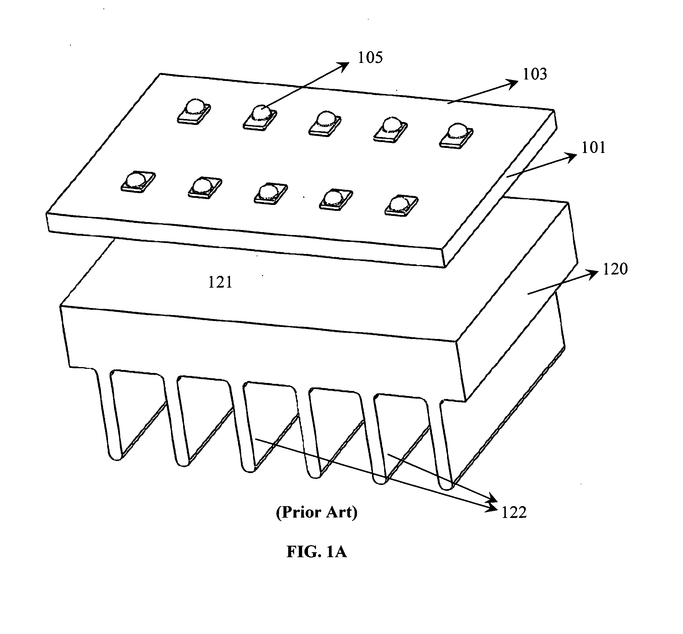
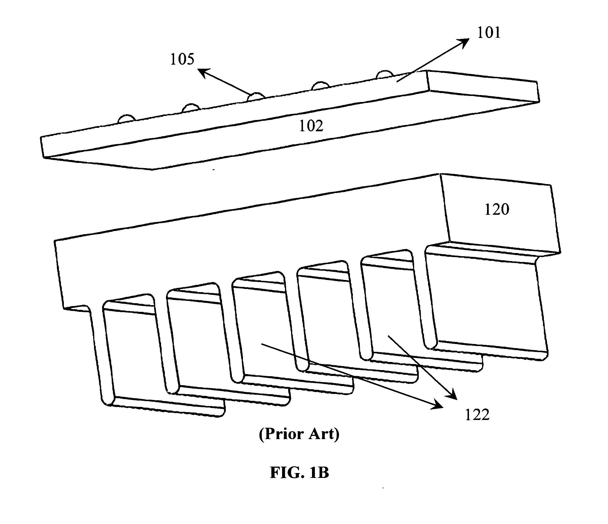
RELATED APPLICATION[0001]This application claims the benefit of priority from U.S. Application No. 61 / 786,513 filed on Mar. 15, 2013, the contents of which are hereby incorporated by reference as if fully set forth herein.BACKGROUND OF THE INVENTION[0002]Virtually all electrical devices contain printed circuit boards with one or more attached electrical components. All electrical components generate some heat that must be dissipated into the environment. This is typically accomplished by mounting the printed circuit board on a heat sink with a generally planar surface. Heat is transferred to the heat sink via conduction. Conduction further serves to spread the heat load throughout the body of the heat sink. At one or more external surfaces, heat is transferred to the environment via convection. Some minor amounts of heat may also be transferred to the environment via thermal radiation. However since heat transfer via radiation is proportional to the difference between the 4th power ...

Claims


Application Information

Patent Timeline
IPC IPC(8): F21V29/76F21V19/00F21V23/00
CPCF21V29/76F21Y2101/02F21V19/0055F21V23/002F21V29/763H05K1/0209H05K2201/066H05K2201/10106F21Y2115/10
Inventor BRETSCHNEIDER, ERIC COLIN
Owner BRETSCHNEIDER ERIC COLIN
Learn More