
Segmented side-to-side faims

a side-to-side faims and faims technology, which is applied in the field of side-to-side faims, can solve the problems of insufficient ion transit time, no force capable of focusing ions in a parallel direction to the electrode surface, and the device side-to-side faims also has limitations

Inactive Publication Date: 2005-07-14
THERMO FINNIGAN
View PDF16 Cites 30 Cited by
  • Summary
  • Abstract
  • Description
  • Claims
  • Application Information

AI Technical Summary

Benefits of technology

The invention provides an apparatus for separating ions using a segmented electrode assembly with multiple electrode segments. The electrodes are arranged in a way that a potential gradient is formed along their length, allowing for the separation of ions based on their movement in the analyzer region. The apparatus includes an inner electrode and an outer electrode with a curved surface, and a carrier gas flow through the analyzer region to direct the ions in a perpendicular direction. The method includes introducing ions into the analyzer region, applying an asymmetric waveform voltage and a direct current compensation voltage to the electrodes, and providing a first and second electric field components for directing the ions in perpendicular directions. The technical effects of the invention include improved separation of ions and improved accuracy of analysis.

Problems solved by technology

Of course, the side-to-side FAIMS device also has some limitations.
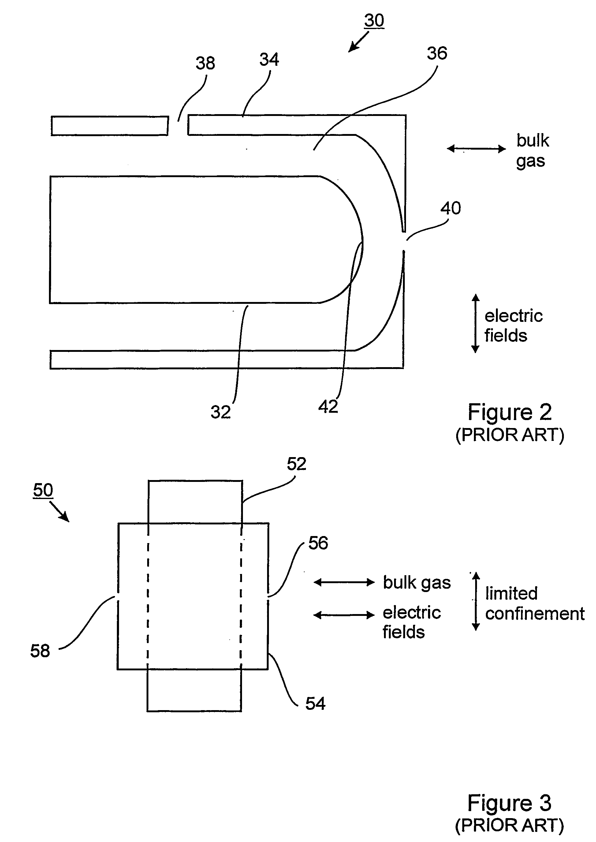
As such, there is no force capable of focusing the ions in a direction that is parallel to the electrode surfaces, i.e. in a longitudinal direction.
The distance between the ion inlet orifice and the ion outlet orifice is also smaller, and may result in insufficient ion transit times to effect separation of a mixture that contains different ionic species having similar high field ion mobility properties.

Method used


Image

  • Segmented side-to-side faims
  • Segmented side-to-side faims
  • Segmented side-to-side faims

Examples


Embodiment Construction

[0035] The following description is presented to enable a person skilled in the art to make and use the invention, and is provided in the context of a particular application and its requirements. Various modifications to the disclosed embodiments will be readily apparent to those skilled in the art, and the general principles defined herein may be applied to other embodiments and applications without departing from the spirit and the scope of the invention. Thus, the present invention is not intended to be limited to the embodiments disclosed, but is to be accorded the widest scope consistent with the principles and features disclosed herein.

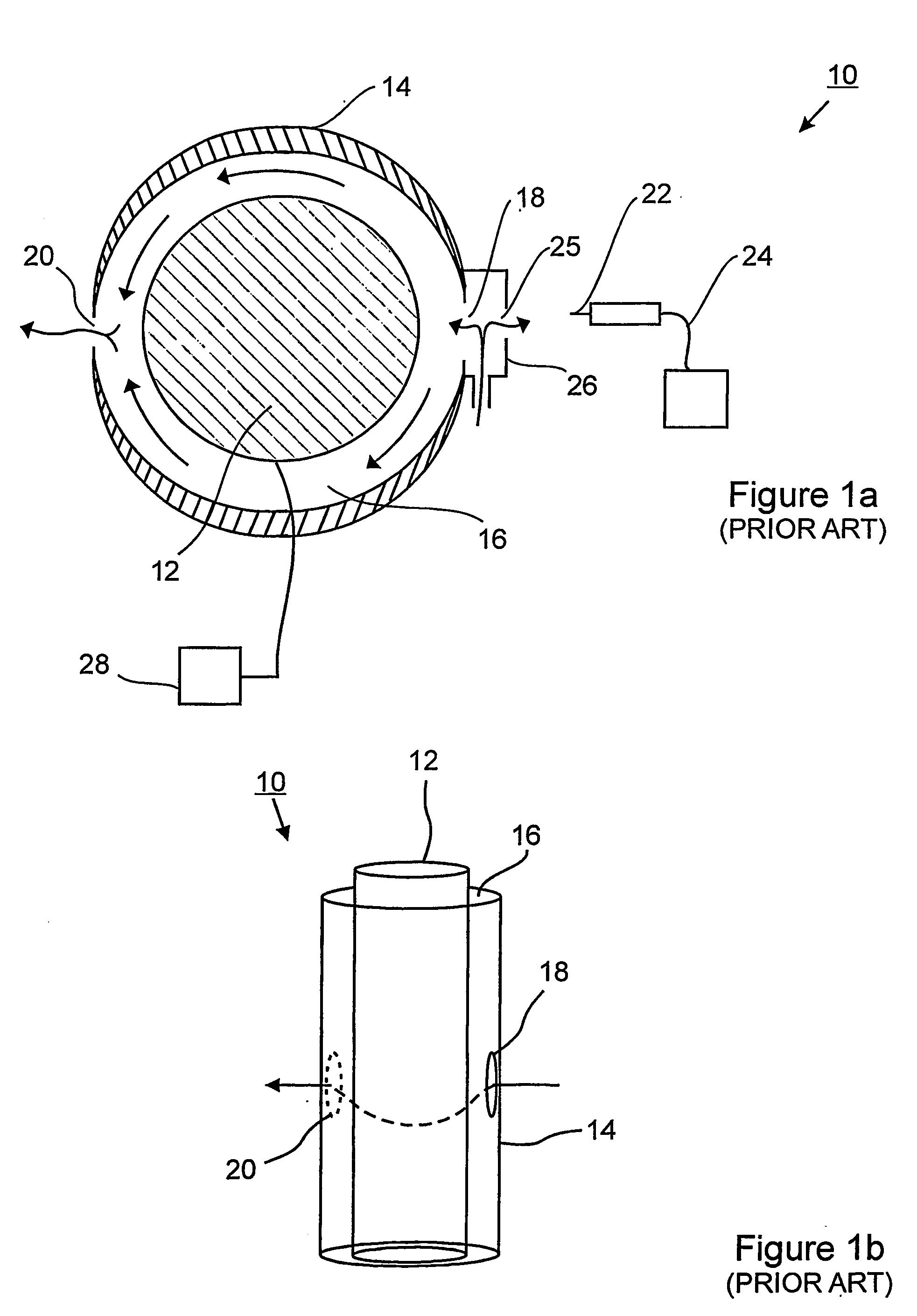
[0036] Referring to FIG. 1a, shown is a simplified cross sectional view of a cylindrical side-to-side FAIMS according to the prior art. The cylindrical side-to-side FAIMS device, shown generally at 10, includes inner and outer cylindrical electrodes 12 and 14, respectively, which are supported by an electrically insulating material (not shown) ...


PUM

PropertyMeasurementUnit
electric fieldaaaaaaaaaa
voltageaaaaaaaaaa
lengthaaaaaaaaaa

Abstract

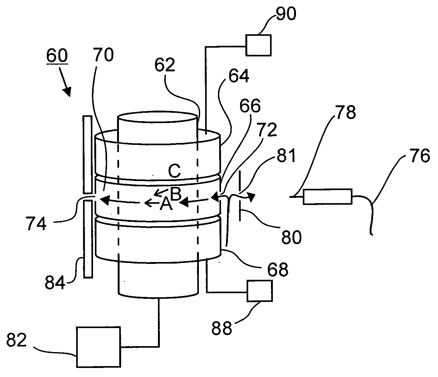
Provided is a side-to-side high field asymmetric waveform ion mobility spectrometer (FAIMS) including a generally cylindrically-shaped inner electrode having a length. Encircling the inner electrode is a generally cylindrically-shaped outer electrode assembly comprising at least first and second and third outer electrode segments. Each of the outer electrode segments has a channel extending therethrough and open at opposite ends thereof. In an assembled condition, the second a outer electrode segment is disposed intermediate the first and third outer electrode segments in an end-to-end arrangement, each one of the first and second and third electrode segments overlapping a different portion of the length of the inner electrode. An electrical contact is provided on at least one of the inner electrode and the second outer electrode segment for receiving a first direct current voltage between the inner electrode and the second outer electrode segment, and for applying an asymmetric waveform voltage to the at least one of the inner electrode and the second outer electrode segment. The second outer electrode segment is maintained at a different potential relative to the first and third outer electrode segments, such that a potential gradient is formed in a direction along the length of the inner electrode.

Description

FIELD OF THE INVENTION [0001] The instant invention relates generally to high field asymmetric waveform ion mobility spectrometry (FAIMS), more particularly the instant invention relates to a side-to-side FAIMS having a generally cylindrical inner electrode and a multi-segmented generally cylindrical outer electrode assembly. BACKGROUND OF THE INVENTION [0002] High sensitivity and amenability to miniaturization for field-portable applications have helped to make ion mobility spectrometry (IMS) an important technique for the detection of many compounds, including narcotics, explosives, and chemical warfare agents as described, for example, by G. Eiceman and Z. Karpas in their book entitled “Ion Mobility Spectrometry” (CRC, Boca Raton, 1994). In IMS, gas-phase ion mobilities are determined using a drift tube with a constant electric field. Ions are separated in the drift tube on the basis of differences in their drift velocities. At low electric field strength, for example 200 V / cm, t...

Claims


Application Information

Patent Timeline
Patent Type & Authority Applications(United States)
IPC IPC(8): B01D59/44G01N27/64H01J49/00H01J49/04H01J49/40H01J49/42
CPCG01N21/35G01N21/65G01N27/624Y10T436/24G01N21/3504Y10T436/105831G01N21/03
Inventor GUEVREMONT, ROGERPURVES, RANDYBARNETT, DAVID
Owner THERMO FINNIGAN
Learn More