Field excitation for an alternator

a field excitation and alternator technology, applied in the field of system control of the excitation coil of the alternator, can solve the problems of affecting the voltage regulation of the electrical system of the vehicle, constant alternator output change, and system load

Active Publication Date: 2005-07-14
VANNER
View PDF19 Cites 23 Cited by
  • Summary
  • Abstract
  • Description
  • Claims
  • Application Information

AI Technical Summary

Benefits of technology

[0006] An aspect of the present invention is to provide a system for rapidly compensating for changes in power demand of a variable load connected to an alternator. The alternator has a voltage source that includes an output and an electrical common, a field coil, a stator coil magnetically coupled to the field coil, and a three-phase rectifier. The variable load is connected to the rectifier. The system comprises a capacitor connected between the output of the voltage source and the common, forming a charge reservoir. A first selectively operable switch is connected between the charge reservoir and a first end of the field coil. A second selectively operable switch is connected between the common and a second end of the field coil. A first catch diode has its anode connected to the common and its cathode connected to the first end of the field coil. A second catch diode has its cathode connected to the charge reservoir and its anode connected to the second end of the field coil. At least one of the first and second switches is operated at a determinable variable duty cycle. The capacitor both absorbs energy from the field coil and supplies energy to the field coil to regulate the magnetic field of the field coil, effective to regulate the output voltage of the three-phase rectifier and rapidly compensate for changes in the power demand of at least one load connected to the three-phase rectifier.

Problems solved by technology

A particular problem of such systems is that the loading of the system and, consequently, the alternator output constantly changes as various engine and ancillary accessories are switched on and off.
This can adversely affect the voltage regulation of the vehicle's electrical system.
The slow response of the alternator to changing load conditions thus results in relatively poor electrical system voltage regulation.
This problem is exacerbated when a number of accessories are randomly switched on and off at any given time.

Method used


Image

  • Field excitation for an alternator
  • Field excitation for an alternator
  • Field excitation for an alternator

Examples


Embodiment Construction

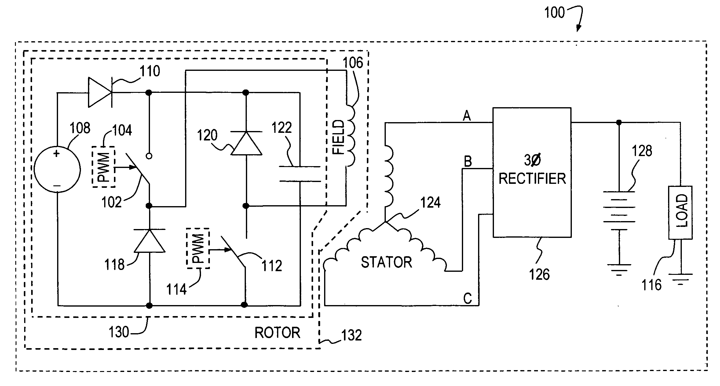
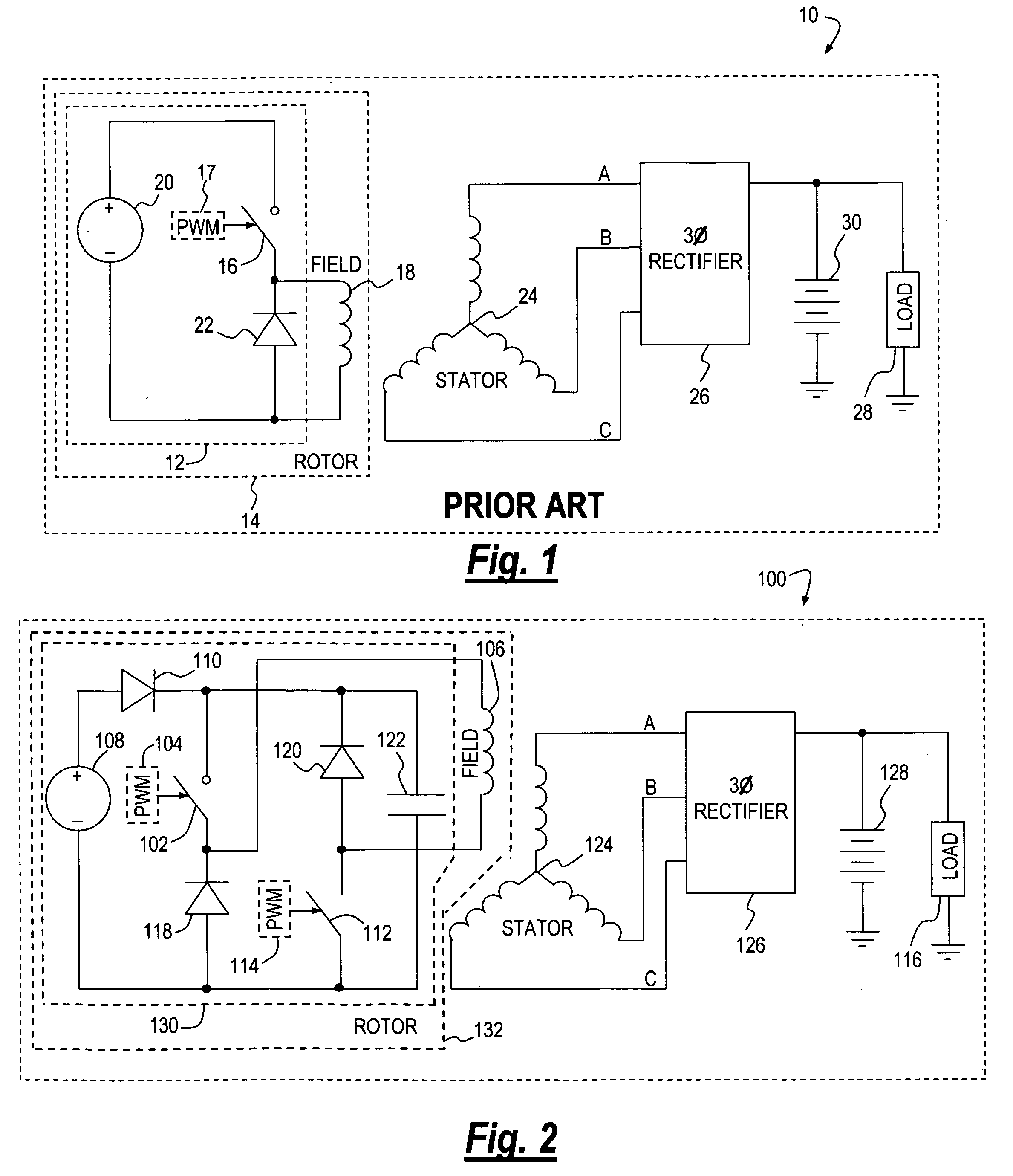
[0017] A typical prior art alternator system 10 is shown in FIG. 1. Alternator system 10 includes a buck-type switching converter field excitation stage 12 and a rotor 14. A conventional electrical switch 16, such as a transistor, field effect transistor or solid state relay is switched open and closed (i.e., OFF and ON respectively) by a pulse-width modulator 17 in a predetermined manner to periodically interrupt electrical current supplied to a field coil 18 by a voltage source 20. A catch diode 22 is placed in parallel with field coil 18 to circulate current in the field coil when switch 16 is open. A three-phase stator 24 is magnetically coupled to field coil 18. Rotation of field coil 18 by a prime mover such as an engine (not shown) causes the field coil to periodically couple to a set of windings A-B-C of stator 24, thus generating a three-phase alternating current in the stator. The three-phase electrical voltage present at windings A-B-C is coupled to a three-phase (“3Ø”) r...


PUM


Abstract

A system for controlling the excitation of an alternator field coil. The system comprises a capacitor forming a charge reservoir, a first and a second selectively operable switch connected to opposing ends of a field coil of the alternator, a first catch diode, and a second catch diode. At least one of the first and second switches are operated at a variable duty cycle and the capacitor both absorbs energy from the field coil and supplies energy to the field coil to regulate the magnetic field of the field coil, effective to regulate the output voltage of the alternator and rapidly compensate for changes in at least one load connected to the alternator.

Description

[0001] This application claims priority to U.S. provisional application 60 / 536,328, filed Jan. 14, 2004, the contents of which are hereby incorporated by reference.FIELD [0002] The present invention relates generally to vehicle electrical systems and, more particularly, to a system for controlling the excitation of an alternator field coil. BACKGROUND [0003] There is a desire on the part of vehicle manufacturers to increase the electrification of vehicle auxiliary loads by reducing the number of engine accessories that depend directly on the fueled-engine as a prime mover. Examples include the vehicle's power steering pump, hydraulic drives, engine cooling fan, air conditioning compressor, oil and coolant pumps, and air compressors. An advantage of accessory electrification is reduced engine loading, which facilitates greater engine performance, increased flexibility in locating the accessories, reduced fuel consumption, more efficient accessory operation, and reduced vehicle emissi...

Claims


Application Information

Patent Timeline
Patent Type & Authority Applications(United States)
IPC IPC(8): H02H7/06H02P9/00H02P11/00
CPCH02M2003/1555H02P9/305H02M3/1555
Inventor ISURIN, ALEXANDERCOOK, ALEXANDER
Owner VANNER
Why Eureka
Try Eureka